Hi,

Your PR has not been rejected (it is still "open" on GitHub) and, as I am writing this message, I still see ONE good reason to accept it (more on that later).
The timing is indeed bad, the explanations provided on this forum could have been more detailed and I understand my intervention upsets you... but those cannot be helped so let us focus on the matter.
I did read your posts on this forum regarding this feature, and I believe you have not explored all the options currently offered by QElectroTech. This was especially reflected by your focus on symlinks (which are one way to get things done but far from being the only way) and the notion that our "workaround" makes you "switch" between collections, which is a misconception.

Essentially, before accepting your PR, we would like to ensure you at least tried the following setup in your company:
https://xavier.kindwolf.org/misc/QElectroTech-enterprise-setup.svg

Basically, the idea is to:

  • copy the QElectroTech official collection to a network share (you can remove categories your company never uses)

  • add your company's elements (typically in a separate directory next to it to keep things clean and tidy)

  • make QElectroTech use that network share as common collection; as mentioned on GitHub, there are several ways to achieve this

That way, end users within your company no longer have to worry about whether an element of yours made its way into the official QElectroTech collection because QElectroTech will show whatever you want it to show (namely "official" elements next to yours).
Technically speaking, the entire setup leverages the fact that collections are just directories: one is meant to be shared, the other is meant to be personal. The QET official collection is just something we provide to fill the shared directory by default.
Since you mentioned the idea of a network share in one of your posts, we believe this setup should be feasible for you. That being said, there may be constraints of yours that we do not see. If so, please explain those extra constraints to us.

The one thing where we still have doubts is performance, since this highly depends on your company's structure (e.g. workstations in Berlin, network drives in Sydney). THIS is the reason that could make the concept of "3rd collection" relevant.

Yet another point we might need to discuss is: if 2 collections are not enough, are 3 actually enough? Should we enable users to add more than one "company collection"? E.g. Service A's collection and Service B's collection?

2

(1 replies, posted in News)

Hello,

First, as usual, a short summary of the work accomplished since the previous news:

  • Our elements collection now provides 1642 elements within 251 categories

  • Our translators worked hard (you can follow statistics on http://qelectrotech.org/wiki/doc/transl … raductions ) so we can announce that, beyond the application itself, the elements collection will be fully (or mostly) translated to the following languages: English, French, Czech, Polish, Italian, and probably Arabic too.

  • The "zoom content" action was added to the diagram editor

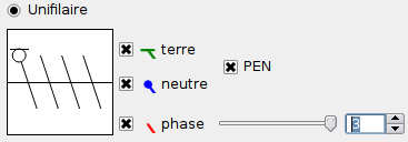
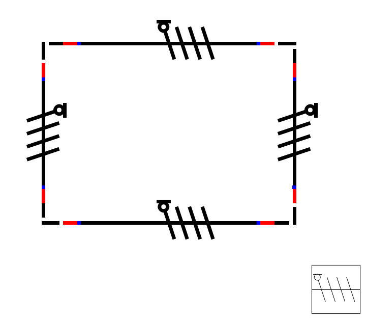
  • Symbols drawn on singleline conductors now feature a "PEN" option, which enables users to merge neutral and ground symbols.

  • Also, conductors could be rendered with either a solid or dashed line; a third style was added: dashdotted line.

  • A handy "Set current date" button was added to the diagram properties dialog

  • The elements panel was slightly refined: it does not hang the application anymore, it gets refreshed in some specific cases and its context menu now features extra actions to interact with real files behind the displayed tree

  • We also added actions in the context menu of selected items so they can be easily edited.

  • One of the biggest technical change is that we began implementing what we call a "decorator" for the element editor, i.e. the ability to have a shiny rectangle around the selected primitives that lets you move and resize them in a friendly way. Unfortunately, it is still riddled with bugs at the moment and it may even not appear in the next release due to the second part of this news item.

As usual, one may notice that it was a long time since the previous news. This bad habit is mainly due to QElectroTech not being my main occupation at all. And, today, this is going to go a bit further, because I, Xavier, main developer of the QElectroTech project, have decided to definitely stop working on it. I first announced (and explained) it via a mail sent to our internal mailing list, which you can read here: English version, French version.
This is of course no good news for you users since "main developer" was actually meaning "single really involved developer".
In concrete terms, this means that the remaining members of the project (contributors to the elements collection, casual developers, translators) will have to organize in order to take over the whole project. To this end, I can announce right now that the project is officially looking for one to several C++/Qt developers, able to dive in the existing code, grasp its abilities and limits, and keep the adventure going.
Until then, a noticeable slowdown is to be expected, especially regarding the release of the long-waited 0.3 version.

Oulah, on se calme.
cfdev : je crois qu'il vaut mieux épurer un peu et ne pas absolument chercher à représenter de manière plus ou moins symbolique tout ce qui constitue QET. Donc personnellement, je ne mettrais ni le dossier (trop figuratif) ni le PLC, parce que 1 - sa perspective fait tache avec le reste et 2 - QET ne fait absolument pas ce genre de rendu.
scorpio: je te décerne le grand prix du splashscreen le plus affreux de tous les temps. Haut la main même...

Salut Cyril,

Au cas où tu l'aurais loupé, mon feedback sur ton dernier essai, à savoir :
http://qelectrotech.org/wiki/_media/qet_splash_0.3.png

[19:59:51] < xavier> Pas mal, les schémas rendent mieux que sur les précédents
[20:00:17] < xavier> T'as du réduire l'icône QET aussi apparemment
[20:00:39] < xavier> ça se sent ça
[20:01:48] < xavier> je suis pas sûr que la diode / lampe qui sort du dossier rende très bien, ça fait un peu "y'avait un blanc, on a comblé comme on pouvait"
[20:02:48] < xavier> à la rigueur s'il fallait remplir cet espace, j'essaierais de reprendre un screenshot d'élément édité comme sur la 0.2

J'en profite pour coller le feedback de Laurent :
[21:02:39] < scorpio810> cfdev: je verrai bien http://openclipart.org/tags/PLC sur le plashscreen
[21:04:16] < scorpio810> http://openclipart.org/detail/103597/pr … y-wetomelo serait pas mal pour remplacer la prise de l'ancien splash
[21:06:30] < scorpio810> http://openclipart.org/people/wetomelo/FPXC14R.svg

Salut,

Le schéma que tu montres a été obtenu en insérant des éléments "Folio suivant" et "Folio précédent" (tape folio dans le champ "Filtrer" du panel d'éléments pour les trouver plus facilement) puis en les reliant par un long conducteur. Ensuite, les éléments adéquats du schéma ont été reliés soit à l'élément "folio suivant" soit à l'élément "folio précédent", en s'assurant que les trajets des conducteurs se recouvrent.

Euh, non, j'infirme : la révision 1944 traite un autre problème découvert pendant que je reproduisais ce même bug, étrangement rapporté une journée plus tôt par un anglophone sur la mailing list. Je voulais corriger ça ce week-end mais c'est mal barré niveau dispos...

Ah, c'est juste ça...
Hélas, en l'état actuel des APIs à ma disposition (QTableWidget, QTableWidgetItem), je n'ai pas moyen d'interférer sur ce comportement. À noter que la même problématique se pose pour l'édition d'une valeur multilingue (dans l'éditeur d'éléments ou de templates).

Sinon si tu peux me décrire plus précisément la démarche à effectuer pour reproduire le bug, je veux bien pousser les tests plus loin...
Note : le build Windows de la révision 1935 est dispo.

Sinon je me disais qu'un petit raccourci genre "aller au folio n°<saisir numéro>"  serait ptet plus simple. Voire même un "aller à" plus sophistiqué, à l'instar de ce qui se fait dans les environnements de développements intégrés (je pense au Ctrl+L de Qt Creator là...)

Salut,

Captaindoc wrote:

Bonjour ici,
Je reviens vers vous pour avoir quelques informations. J'aimerai traduire mon schéma élèc en anglais. Et je ne sais pas comment traduire le nom de page : [---]
Bien sur je pourrais traduire mottamot nomicons/smile mais ce n'est peut être pas judicieux.

Je dirais :
Page de garde => flyleaf
Nomenclature  |  Référence => aucune idée
Mesure_Temperature => temperature probe/measuring (sonde/mesure)
Mesure_Débit => débit de quoi ? de manière générique je dirais flow/output measuring
Implantation => implementation?


Captaindoc wrote:

Je compte sur les pro bilingue du forum.

Hélas, comme indiqué dans une des dernières news, nous n'avons aucun contributeur bilingue (plus exactement : aucun contributeur parlant nativement anglais).

Pour information, ça a été commité, et il devrait bientôt y avoir un nouveau build Windows.

friskolon wrote:

Bonjour,

Je viens de tester la dernière version 1521

Tu veux dire 1921, la dernière packagée pour Windows, la toute dernière au moment où je rédige ce message étant la 1935 ?

friskolon wrote:

Je viens cependant de trouver un bug dans la page :
Je suis parti d'un projet vierge pour faire les tests :

Voici le résultat du test 1 :
je remplis la ligne 1 (nom et valeur), je clique ok, je rouvre, rien n'apparait dans la ligne 1

Voici le résultat du test 2 :
je remplis la ligne 1 et 2 (nom et valeur), je clique ok, je rouvre, ligne 1 ok mais ligne 2 pas de valeur
Et impossible de supprimer la ligne buggée sans valeur

Ça me dit quelque chose, j'ai souvenir d'avoir rencontré et corrigé ce bug, je vais vérifier ce qu'il en est dans le dernier build Windows. En attendant, peux-tu me confirmer la révision que tu as testée ?
Edit : après test rapide sous Windows, cela me semble fonctionnel...

Salut,

friskolon wrote:

Serait-il possible d'intégrer l'utilisation d'une variable (exemple %id) dans le champ titre du schéma comme pour les autres champs.

En fait, en l'état actuel des choses, les valeurs des variables ne sont pas interprétées, %folio est la seule exception à cette règle et seuls %id et %total y sont reconnus.

friskolon wrote:

Dans mon exemple, je n'aurai que les n° de folios toujours à jour, plus facile pour passer du folio 1 à 7 que de faire défiler les titres soit en haut soit à gauche.

En revanche, quand tu crées ton propre template, tu peux renseigner %{folio-id} %{title} en guise de valeur dans la cellule de ton choix, cela aura un effet similaire.

friskolon wrote:

Je trouve difficile de jongler dans les onglets lorsque les titres sont longs, et l'utilisation de la barre de défilement dans les blocs à gauche demande à mon gout trop de manipulations dans les arborescences (réduire-rouvrir) lorsque l'on a une dizaine de folios voire plus.

Hmm, oui, je peux comprendre. faudra qu'on voit si on peut mettre les projets ouverts dans une "vue" à part (ou au pire en double, en n'affichant que les schémas)...

rfr23 wrote:

Juste le petit trait qui serait peut être + visible si il était légerement + large que le rond

Euh... je peux augmenter l'épaisseur du trait, mais si je le fais plus large que le cercle sous-jacent, ça va rendre carrément bizarre.

rfr23 wrote:

et le rond peut être plein comme le neutre  ( ce symbole est un mélange du symbole du neutre et de la terre )

Peut ? Là, par contre, je préférerais un avis plus tranché : plein, vide ou au choix ; de préférence avec une référence genre "telle norme/telle entreprise fait comme ça".

rfr23 wrote:

En anglais c'est aussi PEN,  il s'agit d'un terme anglophone ( Protective Earth Neutral ) mais on utilise ce terme en France.

Merci bien,

rfr23 wrote:

Sinon je suppose que tu vas l'ajouter ici :   http://d21.e-loader.net/hCsfXczpQt.jpg

Si oui, il me paraitrai logique que le petit dessin soit en vert comme pour la terre. Le PEN a avant tout la fonction de protection comme la terre.  ( <-- c'est qu'un détail en passant... )

Je l'ajoute bien ici, mais je me déclare également trop fainéant pour faire une petite icône trop meugnonne juste pour ça ; du coup, ça donne ça tout simplement :
http://xavier.kindwolf.org/img/qelectrotech-pen1.png

Je dois encore peaufiner le rendu du symbole. De plus, je pense que je vais augmenter la taille des symboles unifilaires car je les trouve difficiles à lire avec un zoom 1:1 ou après impression.

Bon, premier jet ; est-ce que ceci conviendrait ?
http://xavier.kindwolf.org/img/qelectrotech-pen0.png

Sinon, et c'est important, j'aurais également besoin de connaître le terme anglophone pour désigner ce truc...

16

(0 replies, posted in News)

Hello,

Here is a short summary of the work accomplished since the release of the 0.3 alpha version:

  • Slightly changed the way the SQLite-based elements cache works to avoid problems with distributions packages.

  • Dropping a file(.qet, .elmt, .titleblock, ...) onto a main window now opens that file.

  • Fixed text position bugs that occurred when changing font size or dropping elements onto diagrams. This is the very kind of bugs that makes us release alphas, betas, etc.

  • Fixed a bug related to application configuration data being saved to project files.

  • Fixed a few UI consistency problems.

  • Added a "+" button to add a new diagram to an edited project.

  • Project tabs now have a close button.

  • Reworked the project properties dialog. It now enables users to set project-wide variables/properties, which can of course be used in title block templates. In case you wonder, same-name diagram-wide properties override their project-wide counterparts.

  • Reworked the way file saving works: the save button now saves all diagrams. Attempts to close the project will pop up a dialog showing all modified diagrams instead of asking many questions in a row. The internal working has also been slightly changed, so that QElectroTech will not systematically rewrite an opened file anymore.

  • We also began working on printing issues: page setup parameters are now saved in the application configuration for each used printer.

While the TODO list for the 0.3 beta version keeps shrinking, we do not have any planned date for its release yet. Stay tuned :-)

Salut,

Ce n'est pas la première fois qu'on me rapporte ce genre de problème ; a priori, c'est bien spécifique à l'impression sur une imprimante physique ; en résumé, certaines imprimantes s'avèrent incapables d'imprimer réellement sur les bords de la zone imprimable qu'elles annoncent. Je viens de recevoir aujourd'hui ma nouvelle imprimante physique ; elle ne présente pas ce problème mais ça va me donner l'occasion de me repencher sur l'impression et les problèmes qui y sont liés.

Hmm, nan, c'est le conducteur qui déconne dans certains cas quand la distance à parcourir est trop courte... faudra que je me penche sur le problème.

Salut,

C'est marrant, c'est comme si l'impression PDF faisait ressortir l'esquisse initiale du SVG -- tu pourrais nous filer le PDF en question ?

Ouais, feature request courante, mais pas triviale à implémenter, donc ce sera pour plus tard.

Il manque en effet un mécanisme de cascade pour avoir des variables project-wide (voire application-wide) => je regarde ça..

Mouais. Et t'as essayé de cliquer, voire double-cliquer sur ces "petits traits" ?

Hello,

jonasstein wrote:

qet appears in two menu items here: One in office, one in graphics. I think it should only be in one of them.

As discussed on IRC, this also occurs for LibreOffice Draw; and this looks reasonable for this kind of software people expect in different categories: some people tell themselves "Hmm, I am going to look for it in the office category because I consider this is office-related" while others think "It must be in the graphics tools category, next to Dia".

jonasstein wrote:

the case of the first letter is not consistent. "Untitled diagram" but  "Diagram Properties"

True. This has been fixed in rev1858. By the way, I would have expected you to use the German translation -- do you?

i can not connect the pins of C4000 ECO (R), but i do not see why.

As mentioned on IRC, the element editor indeed features a checkbox named "Allow internal connections", available through the Edit > Edit orientations menu, which enables end users to add a conductor between an element's terminals.

While I'm not a huge fan of some "fantasy" stuff (e.g. coloured elements), most current symbols come from various professional contexts, including those where "professional" means "deal with reality" more than "respect all existing standards or die". So, unless we collect some feedback like "eh, nice software, but you know, nowadays, everybody sticks to EN60617", I do not think we should remove "fantasy symbols". However, an advanced filtering feature that would take standards into account looks like a good compromise...

Hi,

I'll spare some time to pick up a similar icon. However, I am not sure the vertical layout is such a good idea.