Bonjour,
c'est le même type d’écran sur les deux PC?
Certains ont eut des décalages sur Windows avec des écrans Hidpi connectés sur leur laptop.
Tu peux coller les informations sur ta version, tu la trouveras dans le menu Aide -> A propos.

You are not logged in. Please login or register.
QElectroTech → Posts by scorpio810
Bonjour,
c'est le même type d’écran sur les deux PC?
Certains ont eut des décalages sur Windows avec des écrans Hidpi connectés sur leur laptop.
Tu peux coller les informations sur ta version, tu la trouveras dans le menu Aide -> A propos.
Thanks Anthony. ![]()
Yes off course is a patch based on old Subversion, please use
git clone git://git.tuxfamily.org/gitroot/qet/qet.git qet_gitOr fork https://github.com/qelectrotech/qelectr … rce-mirror
La dépêche sur Linux.fr https://linuxfr.org/news/sortie-de-qelectrotech-0-7.
====== ChangeLog from 0.6 to 0.7 ======
* Element editor :
* Element informations (manufacturer, reference etc...) can be created directly from the element editor. For that go to the widget "Element Property"
* It is no longer required to have a text field, for save the edited element.
* Improve the behavior with the arrow keys (depending to the current selection (nothing / one / several).
* Context menu display only enabled actions.
* Added new feature -> alignment.
* Alignment of text field can be edited.
* Added two new actions in context menu for insert or remove point of a selected polygon.
* Rectangle can have rounded corner.
* Polyline: finish the creation of polyline with the last point at the same position of the first point, close the polyline.
* Diagram editor :
* Conductors can now be drawn with two colors.
* Improve High-DPI support on Windows and Linux plateform.
* The code for the resize handles has been almost completely redesigned.
* Dissociate fonts policy and size for independent text item and for summarry pages (foliolist), added a 2 button in config page for open Qfontdialog widget and choose policy for independent text item.
* Add in config page a Qfontdialog widget for change dynamic text size, font family, orientation angle and text length, by default.
* Basic shape add new CustomDashLine style with Dash Pattern (<< 10 << 10 );
* It is now possible to add a text field to an element directly from the diagram.
* Element text item with are now converted to dynamic element text item.
* Element editor, part text can't be edited directly.
* User can export / import the configuration of the texts and texts group of an element.
* Context menu display only enabled actions.
* Added new action in the context menu, multiple paste, check box for autonum the pasted element.
* Multipaste -> improve the conductor autonum, conductors are numerated from top to bottom, and left to right.
* Text of conductor can be placed at top/bottom/left/right of conductor, and text never overlaps the conductor.
* Function for search conductor at the same potential.
When the search function is searching in a terminal element, they search only for the first terminal found, no matter if the terminal element have more than two terminals.
So the list of conductors at the same potential is missing some conductors.
This commit fix it, now the search function search for every terminals of a terminal element.
* When remove an element with several conductors connected to the same terminal, the electrical potential is partially or totally destroyed.
This commit fix it : When element is removed one or several conductors are created (if needed) to conserve the electrical potential.
* Added new feature -> alignment.
* Alignment of text field can be edited.
* Added new context menu action "group the selected texts".
* Widget used to edit text item group can edit the pos of the group.
* Element text item group can now be framed.
* Added two new actions in context menu for insert or remove point of a selected polygon.
* QETshapeItem rectangle can have rounded corner.
* Add in config the possibility to start the numbering of the columns of titleblocks at 0.
* Add new function Search and replace widget Crtl +F
* Diagram properties, Element properties, Independent text item can be changed (and mass changed) through the search and replace widget.
* Added 4 tools for edit the depth (Z value) of items.
* Element panel : elements can be searched by their name but also with by all their informations.
* New free selection style.
* Diagram editor : dock used to edit the shape item, can now edit several items in the same time.
* Dynamic element text item : The font of the dynamic texts can be individually be setted.
* Adding or revoming diagram set project to modified
* When user cleanning an project, set project to modified
* Add a shortcut "Ctrl+Shift+P" to quickly open the dialog used for create the auto numbering rules.
* Add missing StatusTip of some QAction
* When user add a polygon, a message in statusBar show how to finish this shape
* Polyline: finish the creation of polyline with the last point at the same position of the first point, close the polyline.
* Plug-in : Add StatusTip instruction for install and launching DXF plugin depending on the operating system
* when plugin qet-tb-generator"generate terminal blocks and connectors" isn't installed show an QMessageBox instruction now depending on the operating system for install it
Add in QMessageBox url encoding/decoding for easy download packages
* Elementspanelwidget: adds keyboard shortcuts to quickly move up, down,or move the targeted folio to the beginning of the project
F3 MoveUp
F4 MoveDown
F5 MoveUpTop
* Title block editor :
Added new title block variables %projectpath, %projectfilename, %projecttitle, previous-folio-num and next-folio-num
"%saveddate, %savedtime, %savedfilename and %savedfilepath" they variables should be updated after file save or save as dialog is confirmed,
before file is saved.
* NameList widget : add a combo box for easily paste texts, like the variables for title block.
* The font of the dynamic text field can be edited.
* The font of the static text field can be edited.
* The color of the static text field can be edited.
* Improve for new qet_tb_generator plug-in : added the full path of the current project as
an argument when calling the plug-in from QET if a project is open.
If not a file dialog is showed to select the QET project.
* QET create a backup file, use to restore the project when a crash occur.
* Use KAutoSaveFile for the backup system, instead of home made function.
* Use of QSAveFile instead a QFile.
* User can enable and edit autosave timer.
* let user define the file system path of the common,custom elements collections, and custom title blocks template.
* QetGraphicsItem, remove the function applyRotation and rotateBy, and use instead the native function of QGraphicsItem : setRotation
* Conductor is an herited class of QGraphicsObject, instead of QObject and QGraphicsPathItem
* Clean (and reduce the size) the class QETDiagramEditor, mostly by replacing the connection syntax "signal -> slot" by "signal -> lambda".
* Replace deprecated QMatrix by QTransform.
* DXF export : fix some double items in dxf file.
* DXF export : add some colors for basic shapes inside dxf.
* Bug fix :
* Fix compilation warning (clang and gcc).
* Fix element text item alignment work well when text rotation != 0.
* Fix crash when the properties of a element text item group
* Fix crash occurred by the conductor and shape "ghost".
* Fix element text alignment work also when font size change.
* fix :
1- When open a .qet by double click on it, QET ask user for open the backup file, of this .qet.
2- On windows, if user open a project from the recent files menu, when close QET the file is deleted  user lose her work.
clear the element texts when paste an element with the option "Do not store the labels of items in the copy paste" enabled.
* elements can't be moved up and left, when there rotation are different than 0.
* minor fix : slave link dialog doesn't display the good label, when the label of master element is build from formula.
* Fix : in some condition, dynamic text are not at the same position when open a project.
* On windows when user drag and drop an element from the common elements collection to the custom elements collection,
the element file stay in read only mode, and so user can't save the element
* Improvement : minimize the unwanted gap of the top right folio of the view (see https://qelectrotech.org/forum/viewtopi … 379#p9379)
* Fix: bug 168
* Fix : when create multiple conductors with the free hand selection, the checking of existing potentiel don't search trought a folio report.
* Fix: DXF export.
* Minor fix : remove from the element information the html hexadecimal and decimal characters of line feed and carriage return.
* fix : in the diagram editor, when we select several shapes at the same time, the properties widget only apply the change to one shape.
* Bug fix : when user load a project which contains summary pages, project was marked modified (summary was created on the fly and moved from the end on second
position), now the project is no longer marked as amended when user have one or multiples summary pages when loading this project.
* Static text of element are now exported to dxf
* Fix Static text size of element exported to dxf
* Improvement : minimize the unwanted gap of the top right folio of the view
* Fix : when create multiple conductors with the free hand selection, the checking of existing potentiel don't search trought a folio report.
* Don't display gui when qet is launched
Pour le téléchargement ça ce passe ici en attendant que je mette à jour les liens sur la page officielle :
https://download.qelectrotech.org/qet/tags/20190717
Pour les packageurs mainstream les tarballs se trouvent ici:
https://git.tuxfamily.org/qet/qet.git/tag/?id=0.7.0
Enjoy ! ![]()
Bonjour Arnaud tu es le bienvenue ici.
Bon soir,
sur la chaîne YouTube, tu trouveras quelques exemples en vidéo :
Pas besoin ici de clore un sujet. ;-)
Il y a quelques exemples de projets ici :
https://download.qelectrotech.org/qet/schemas_pdf/
Hello Stromie,
we thinking is better in project cross-reference settings, Joshua want to guide you.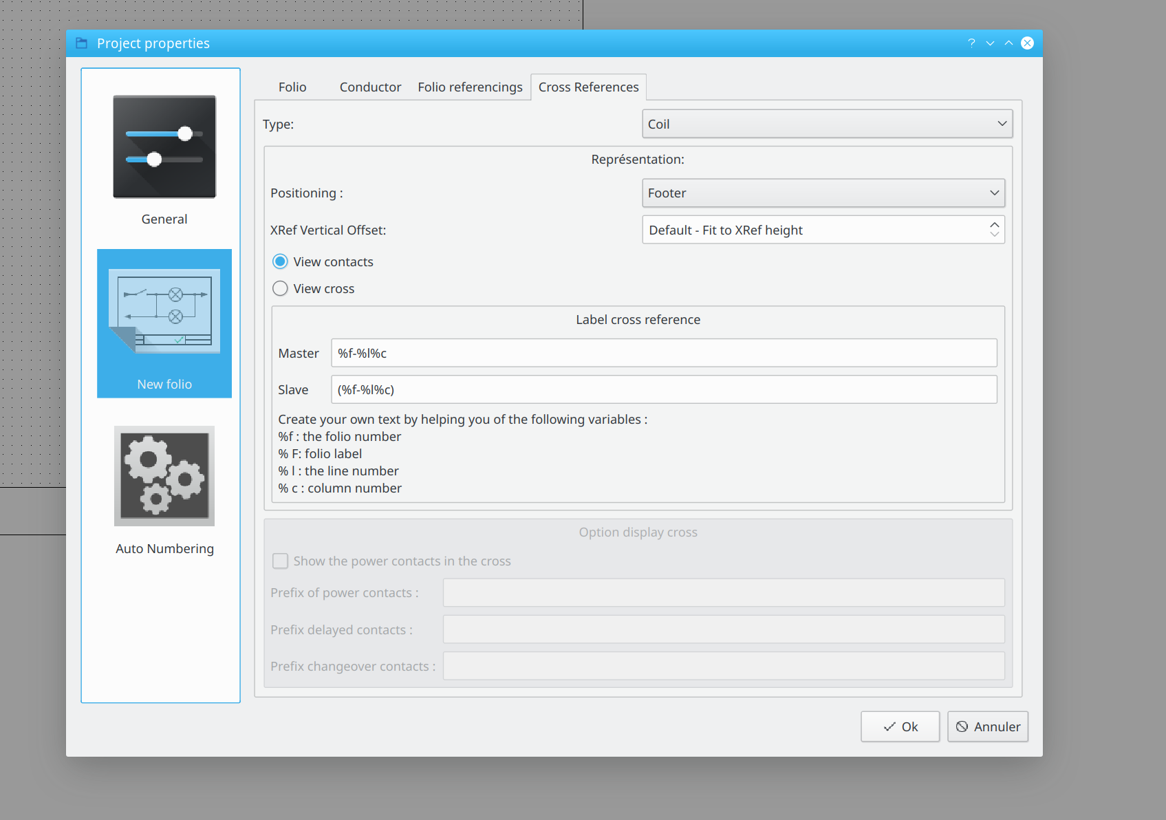
Ajouté, Merci.
Nice, thanks Stromie. ;-)
You're right, look in sources/ui/configpage/generalconfigurationpage.cpp.
Great ! You could send patch?
What do you want to do make it in static? For packaging In shared mode, just create a bin directory and copy DLLs them in, like this old example :
https://qelectrotech.org/wiki_new/doc/d … mande_tree
Maybe the problem is if KF5 libraries isn't builded with the same Qt version than you compile QET?
Bonjour,
nous avons le plaisir de vous annoncer la sortie de la version 0.7 après plus d'un an de travaux.
Retour sur la 0.6 Annonce de la version 0.6
Dans les grandes lignes :

Refonte totale du panel des collections d'éléments, avec de nouvelles possibilités de filtrage ;
Réduction drastique de la consommation RAM (grâce au nouveau panel d'éléments) ;
Utilisation du multi-threading lors du chargement de la collection d'éléments.
Ces trois améliorations font partie d'un même travail de fond, qui a représenté beaucoup de temps.
Règle de numérotation automatique poussée, générateur de folio, folios non consécutifs ;
Diverses améliorations des formes basiques (carré, ellipse…) ;
Nouvelles propriétés épaisseurs de trait pour les conducteurs (souvent demandé) ;
Copier/coller entre projets (demande de longue date) ;
Nouveau thème d’icônes (Breeze de KDE) ;
Rétro-portage depuis la 0.7 d'une correction d'un crash très chiant de QET.
Et comme toujours diverses améliorations et corrections.
Version 0.7
Fil de discussion durant le développement de la version 0.7.
La version 0.7 devait initialement être une version de polissage, dans le but d'effacer les divers petits défauts, qui parfois demandent beaucoup de boulot. Mais en cours de route, les petites choses deviennent grandes et la version 0.7 n'a plus rien à voir avec sa grande sœur.
Correction du crash des « conducteurs fantômes »
Il existait dans QET un bug, lié à la bibliothèque Qt, qui provoquait un crash systématique. Celui-ci était prédictible dès lors qu'un conducteur ou une forme simple qui était effacée, restait affichée à l'écran et provoquait des artefacts lors du survol de la souris ou du changement de zoom. Il a finalement été corrigé et rétroporté.
Textes d'éléments éditables

L'un des gros changements de cette version est la gestion des textes d'éléments. Dans les versions précédentes, les textes d'éléments étaient créés depuis l'éditeur d'éléments. Une fois l'élément posé sur l'éditeur de schéma, la seule possibilité offerte à l'utilisateur était de modifier le contenu du champ texte.
Avec les nouveaux textes, il en est tout autrement :
Premièrement, les textes peuvent être ajoutés ou enlevés à la volée depuis l'éditeur de schémas, ce qui est énorme par rapport aux versions précédentes, mais les améliorations ne s’arrêtent pas là.
Les textes peuvent avoir trois sources :
Texte utilisateur : un simple texte écrit directement par l'utilisateur ;
Information d'élément : le texte affiche l'une des informations de l'élément (label, commentaire, fabricant, etc.) ;
Texte composé : il s'agit du mélange des deux.

On dispose désormais de grands pouvoirs :
Taille de texte ajustable ;
Police de texte modifiable ;
Couleur de texte ;
Pouvoir encadrer le texte ;
Définir la largeur maximale du texte afin de forcer le retour à la ligne ;
Édition de la position (X, Y) au pixel près depuis le widget de propriété de la sélection ;
Édition de la rotation depuis le widget de propriété de la sélection ;
Justification du texte.
Groupe de textes
Les textes peuvent être groupés afin de les manipuler plus facilement. Les groupes proposent aussi quelques options :
Alignement des textes au sein du groupe (gauche, centré, droite).
Édition (X, Y) au pixel près depuis le widget de propriété de la sélection ;
Édition de la rotation depuis le widget de propriété de la sélection ;
Ajustement vertical : correspond à l’espacement vertical entre les textes quand ceux-ci sont alignés ;
Encadrer le groupe ;
Forcer la position en bas du schéma (afin de garder un comportement existant avec les anciennes versions).

Import-export des configurations de textes
Dans un schéma électrique, la disposition, la taille et les autres aspects visuels des textes sont souvent identiques. Afin d'éviter d'avoir à éditer des textes d'élément pour au final toujours leur donner la même configuration, il est possible d'exporter ou d'importer une configuration de texte. Cela permet un gain de temps non négligeable.
Compatibilité avec les anciens textes
Les nouveaux champs textes n'étant pas compatibles avec les anciens, ces derniers ont simplement été supprimés du code (permettant par la même occasion de mieux découper le code).
Lors de l'ouverture d'un projet créé avec une version antérieure, une moulinette fait la conversion entre anciens et nouveaux textes de manière transparente pour l'utilisateur.
Malheureusement, le code des anciens textes possédait beaucoup de rustines afin d'être rétrocompatible, ce qui provoque des défauts de positionnement lors de la conversion et au pire la perte de textes sur des vieux projets (0.3 et 0.4).
Donc un conseil, si vous ouvrez un projet d'une version antérieure : faites une copie (ce conseil est aussi valable pour les photos des enfants à la plage, documents importants, etc.).
Et l'éditeur d'éléments dans tout ça ?
Toutes les possibilités offertes avec les nouveaux textes depuis l'éditeur de schémas, le sont aussi dans l'éditeur d'éléments. Étant donné que les textes peuvent être ajoutés à la volée, il n'est dorénavant plus obligatoire d'avoir un champ texte label pour pouvoir sauvegarder un élément.
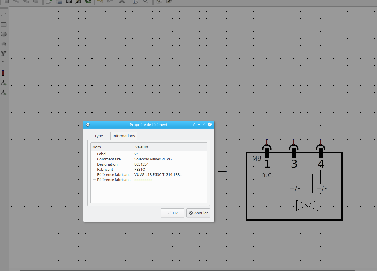
Il est également possible de pré-remplir les informations d'un élément dans l’éditeur.
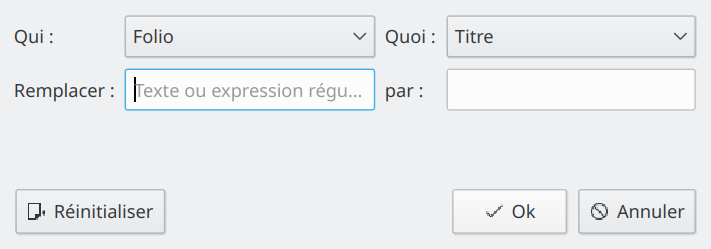
ModifierRechercher, remplacer
Il s'agit du second gros changement de cette version, le célèbre rechercher-remplacer, déjà présent dans beaucoup de logiciels. Un habituel ctrl+F permet d'ouvrir le widget en question. La recherche s'effectue sur :
les folios ;
les textes de folio ;
les éléments (eux-même triés selon leur type : maître, esclave, etc.) ;
les conducteurs.
Il est ensuite possible de modifier et/ou ajouter des propriétés, soit une par une, soit en masse sur les sélections en cours. L'outil peut aussi tout simplement servir à retrouver rapidement un élément (pas facile dans un projet de plus de 200 pages).
Un bouton « Avancé » permet de chercher et remplacer un texte de propriété ou d'utiliser une expression régulière (diagramme, élément, conducteur, texte de diagramme).
Vidéo de présentation
Récupération et sauvegarde automatique
Un système de récupération a été mis en place.
Lors du lancement de QET suite à un crash, une boite de dialogue propose d'ouvrir le fichier de restauration limitant ainsi la perte de travail. Parallèlement, une fonction de sauvegarde automatique à intervalle régulier a été créée (le code étant en partie le même que celui de la restauration).
L'intervalle de sauvegarde est paramétrable, ou désactivable.
Chemins des collections d'éléments
Le chemin par défaut des collections d'éléments (commune et perso) peut être modifié. C'est aussi valable pour les cartouches utilisateurs.
C'était une demande récurrente de la part des utilisateurs.
À noter qu'il n'y a pas de prise en charge réseau, pour cela il faudra passer par un partage de dossier, par exemple Samba. Mon manque de connaissances en matière de réseau et les limites de Qt sur ce point ont eu raison de moi.
La porte est ouverte si une âme charitable pouvait nous éclairer sur ce sujet.
Multi-collage
Un petit outil accessible depuis le menu contextuel permet de coller plusieurs fois une sélection avec un décalage en une seule opération. Lors du multi-collage, il est possible de connecter automatiquement les éléments, ainsi que de continuer les numérotations automatiques des éléments et conducteurs.
Vidéo de présentation
Autres nouveautés
Conducteurs bicolores ;
Position des textes de conducteurs paramétrables (gauche/droite/haut/bas, par rapport au conducteur) ;
Lors de la suppression d'un élément sur lequel plusieurs conducteurs sont raccrochés sur une même borne, le potentiel électrique n'est plus détruit;
Ajout d'un outil "main libre" ou RubberBands permettant une sélection à main levée d'une zone et de connecter automatiquement les bornes sélectionnées par des conducteurs ;
Édition de la coordonnée Z des items dans l'éditeur de schémas (avant/arrière-plan) ;
Possibilité d'arrondir les angles d'un rectangle (éditeur de schémas et d'éléments) ;
Possibilité d'ajouter et supprimer les points d'un polygone (éditeur de schémas et d'éléments) ;
Les informations d'élément (fabricant, fournisseur, référence, etc.) peuvent maintenant être renseignées depuis l'éditeur d'éléments ;
Ajout de nombreuses variables pour les cartouches (%projectpath, %projectfilename, %projecttitle, %previous-folio-num, %next-folio-num), et de variables mises à jour seulement lors de l'enregistrement du projet (« %saveddate, %savedtime, %savedfilename, %savedfilepath ») ;
Une liste déroulante a été créée dans le dialogue de création de texte de l'éditeur de cartouche, afin de pouvoir coller une variable rapidement et sans erreur ;
Ajout dans la config de QET du choix de police et de taille par défaut pour les textes simples, les pages sommaires, et les textes dynamiques ;
Possibilité de travailler avec des cartouches dont l'index des colonnes commence à 0 ;
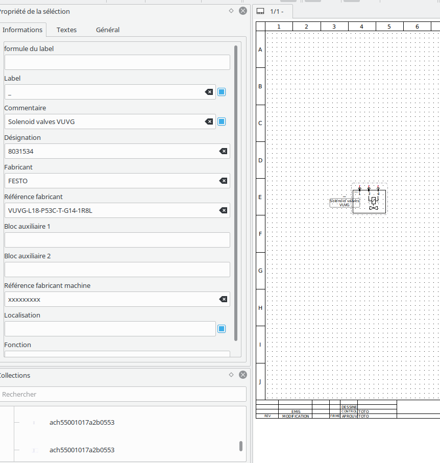
Le panneau latéral Propriétés de la sélection peut maintenant éditer les propriétés des textes indépendamment de l'éditeur de schéma, il permet aussi d'éditer plusieurs textes à la fois ;
La police des textes indépendants peut maintenant être modifiée ;
Le panneau latéral Propriétés de la sélection peut maintenant éditer les propriétés de plusieurs formes simples en même temps.
Polissage
Comme toujours, chaque sortie d'une nouvelle version s'accompagne de divers polissages et petites corrections de bugs, dont entre autres :
Lors du chargement d'un gros projet, la barre de progression figeait vers la fin. La barre de progression reflète mieux l’avancement de l'ouverture du projet ;
La navigation avec les flèches du clavier a été améliorée ;
Amélioration de la prise en charge des écrans HiDPI ;
Amélioration de l’algorithme de recherche des conducteurs au même potentiel ;
Lors d'une recherche dans le panel d'élément, en plus du nom, les éléments sont aussi filtrés par leurs informations (fabricant, référence, code interne, etc.) ;
Grâce au travail de Re-searcher, la densité de la grille de l'éditeur de schéma peut être modifiée, ainsi que le pas lors du le pas lors du déplacement au clavier.
Ajout de nombreux messages dans la barre d’état épaulant ainsi les nouveaux utilisateurs dans la découverte de certains outils de dessin.
Refonte de la boite de dialogue si le greffon Python "générateur de bornier" n'est pas trouvé ou installé, les instructions pour installer le greffon sont différenciées en
fonction du système d'exploitation, des liens cliquables ont été insérés, ils facilitent le téléchargement des bibliothèques nécessaires et du greffon.
À côté du code
Durant le développement de la version 0.7, Laurent, en plus des paquets Debian/Ubuntu, Windows et macOS, fournit maintenant des AppImage de QET. Les versions 0.5, 0.6, 0.7 et développement sont disponibles en AppImage.
En plus de l'avantage de pouvoir utiliser QET sur toutes les distributions prenant en charge AppImage, cela permet aussi d'avoir plusieurs versions de QET, et d'éviter ainsi des problèmes de rétro-compatibilité, avec un projet créé sur une autre version que celle disponible dans les dépôts de votre distribution.
Un paquet au format snap et aussi disponible grâce à la contribution de Max. Discussion sur le forum.
À l'heure actuelle, aucune version de QET au format flatpak n'est encore disponible, mais Mathieu y travaille.
Discussion sur le forum de QET
Une cagnotte leetchi a été créée afin de permettre à Laurent de s'offrir une nouvelle machine de build.
Nous avons ajouté des dépendances vers les bibliothèques KF5 (kdeframework) comme libkf5widgetsaddons, libkf5coreaddons, et sûrement plus tard libkf5archive et d'autres… ceci hélas complique énormément les travaux d'empaquetages de Laurent sur les différents OS en cross-compilation.
À la date du 19 Juillet 2019, QET dispose de 5320 éléments, répartis dans 717 catégories. Une quantité écrasante des éléments fournis par QET provient des utilisateurs qui nous font part de leurs propres éléments afin d'étoffer la collection officielle !
L'interface est traduite dans 21 langues (partiellement ou totalement, les traductions étant faites bénévolement, majoritairement par des contributeurs externes au développement de QET). De nouvelles traductions font leur apparition dont le Hongrois et le Turc.
Une refonte de la documentation est en cours d’écriture, elle est toujours basée sur le logiciel Sphinx : Documentation
Pas besoin d'être développeur pour contribuer à l'évolution de QET ![]() .
.
Version 0.8
Les fonctionnalités manquantes à QElectroTech sont toutes plus ou moins aussi importantes les unes que les autres.
C'est pourquoi nous avons mis en place chez nos amis de framasoft un petit questionnaire des fonctionnalités que les utilisateurs souhaitent avoir en priorité.
Le résultat de ce questionnaire définira la feuille de route de la version 0.8
Page de vote en français
Page de vote en anglais
Dans les grandes lignes on peut noter :
Générateur de borniers natif (un greffon Python existe, rendez-vous dans le menu « projet -> lancer le greffon de création de bornier ») ;
Générateur de câbles ;
Outils de traduction des projets ;
Structure de projet selon la norme IEC 81346.
Le futurn'est bien sûr pas figé et continue d'évoluer au fil des retours utilisateurs.
En résumé
Sans conteste, QET propose nettement moins d'outils que les logiciels phares de ce domaine (EPLAN Electric P8, SEE Electrical, SchemELECT et beaucoup d'autres). Entre autres, il manque certaines fonctions de base que l'on est en droit d'attendre pour ce genre de produit, telles que la création de câbles, l'identification de structures selon la norme IEC 81346.
Pour autant et malgré ces lacunes, QET a de plus en plus d’utilisateurs professionnels pour les raisons suivantes :
il répond aux principaux besoins des professionnels sans nécessiter une longue formation ;
il n'impose pas de coûts de licences exorbitants (le GPL étant aujourd'hui un peu moins taxé que ses concurrents) ;
il prend en compte les retours des utilisateurs, en général sous 1 à 2 semaines, parfois même le lendemain pour les petits détails ; dans le cas contraire, les demandes vont directement dans la todo list.
L'équipe de QElectroTech tient à remercier toutes les personnes qui nous encouragent dans ce projet, que ce soit par des remerciements, dons, propositions, retours de bug et d'utilisation.
Si ce n'est déjà fait, je vous laisse visiter ce lien et juger par vous-même des divers schémas présentés. Ce schéma (d'une vraie installation industrielle) est représentatif des possibilités offertes par QET.
Cette dépêche a été écrite par Joshua et en collaboration sur le site Linux.fr https://linuxfr.org.
Bonjour,
en principe on part du sectionneur général et on tire les conducteurs horizontalement avec des renvois sur tous les folios puissance, apes plus qu'a raccorder chaque alim.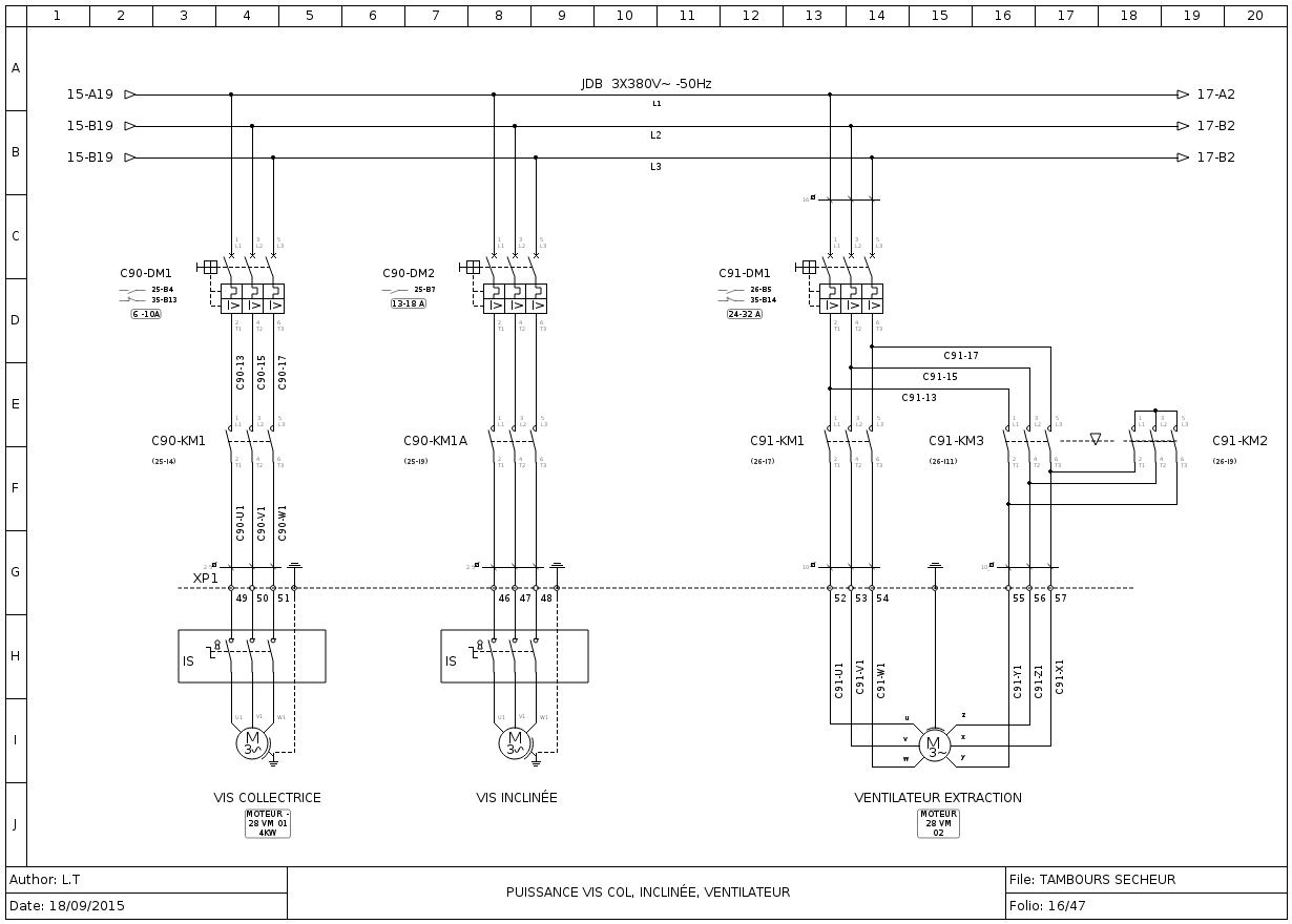
Cool ;-)
Thanks for compliments.
Isn't the latest, please upgrade, thanks.
5749 is build the 24/02/2019.
Bonsoir Didier,
Quelle version faut-il prendre pour Windows 10?
La version 0.7RC2 est le bon choix.
J’ai installer la version 0.70 RC2, mais il y a deux possibilités.
Il y a la version normale avec installateur, et la version ReadyToUse dite portable (idéale sur une clé USB et qui ne nécessite pas d'installation)
Y as t-il un autre programme a installer en complément?
Oui, il y a deux programmes qu'on peut installer en plus, le convertisseur DXF pour convertir des symboles DXF en symboles QET et un générateur de bornier.
Dans un premier temps, je fais ma distribution en tétra (sortie de mon inter sectionneur général) à l’horizontal, puis je pose mes différents disjoncteurs.
Pour faire mes liaisons, il me faut tirer mes alims manuellement.
Y a t’il un autre moyen de faire?
C'est la seule façon de faire pour les départs, relier chaque borne de tes disjoncteurs sur les bornes de ton inter sectionneur général, les conducteurs seront automatiquement dessinés verticalement et reliés par des points a ta distribution (conducteurs horizontaux).
Comment fait-on pour nommer nos différents éléments?
Quand on clique sur un élément un widget "propriété de la sélection" s'ouvre pour renseigner les informations de l’élément.
Petite remarque en passant:
Lorsque je lance une recherche dans l’onglet dédié (sur la gauche, au dessus de la fenêtre des éléments), le programme plante et ne réponds plus.
Ça peut prendre un peu de temps au début et sur la première recherche, même sur une machine puissante.
Idem pour la numérotation des fils sur la partie télécommande, je pensais que cela se faisait automatiquement.
Oui, ça peut se faire automatiquement.
Je souhaite faire un tableau avec un système de bobine MX mais je ne trouve pas cet élément dans la liste de matériel.
Il est très facile de faire ses propres éléments, il y a un éditeur fourni qui permet de modifier un élément ou d'en créer un depuis zéro ou a partir de morceaux d'autres symboles.
Lorsque je pose un disjoncteur différentiel en tri et que je lui colle un contacteur en sortie, les liaisons auto ne se font que sur les deux premiers pôles, visiblement le logiciel ne prends pas en compte le troisième pôle.
Les bornes ne doivent pas être en face sur le troisième pole?
Quelques liens qui te permettront de découvrir le logiciel :
https://www.youtube.com/user/scorpio8101/videos
https://qelectrotech.org/forum/viewtopic.php?id=1075
https://download.qelectrotech.org/qet/j … l/QET.html
https://download.qelectrotech.org/qet/m … index.html
Cordialement,
Laurent
I f you try new project under 0.7 and only drag and drop the schneider Altistart01N2 Element, save it and re open it, texts are changed?
Please paste QET version.
On 0.7 you could change texts fonts policy on the fly in QET settings, just relad project to see changes.
BTW, 0.7 not change your project texts size when you launch 0.6 or 0.7 version.
You could provide project or captures?
Cheers,
Laurent
Bonjour,
les paquets Windows ainsi que l'AppImage sont maintenant compilés avec la dernière version du framework Qt soit 5.13.0.
Yes, .exe files contain dll in static mode, that's why it's bigger than you in shared mode, but if you count dll size is the same thing.
Maybe if you could provide a guide for those who wants to compile it under Windows, it could be useful.
QElectroTech → Posts by scorpio810
Powered by PunBB, supported by Informer Technologies, Inc.
Generated in 0.082 seconds (24% PHP - 76% DB) with 5 queries