
Thanks for your feedback.
3,676 2019-11-27 20:52:46
Re: Qelectrotech is lagging all the time (5 replies, posted in EN : Help, suggestions, discussions, ...)
3,677 2019-11-27 20:50:56
Re: Pb ouverture d'un fichier QET (13 replies, posted in FR : Aide, suggestions, discussions, ...)
3,678 2019-11-27 20:49:20
Re: Pb ouverture d'un fichier QET (13 replies, posted in FR : Aide, suggestions, discussions, ...)
Bonjour Ran,
si tu peux mettre ton projet ici, on pourra regarder ce qui bloque.
3,679 2019-11-26 15:18:10
Re: QElectroTech howto found on the WWW (53 replies, posted in Videos howto)
3,681 2019-11-25 15:22:04
Re: Nouveautés de la version de développement 0.8 (317 replies, posted in News)
Bonjour,
pour ceux que ça intéressent "déploiement réseau", Christophe Admin du site MyEleec a crée un package MSI de QET :
3,682 2019-11-21 18:25:49
Re: Discussion sur l'export CSV (58 replies, posted in FR : Aide, suggestions, discussions, ...)
Le format d'enregistrement des requêtes SQL dans le json a changé, te faudra recréer tes requêtes :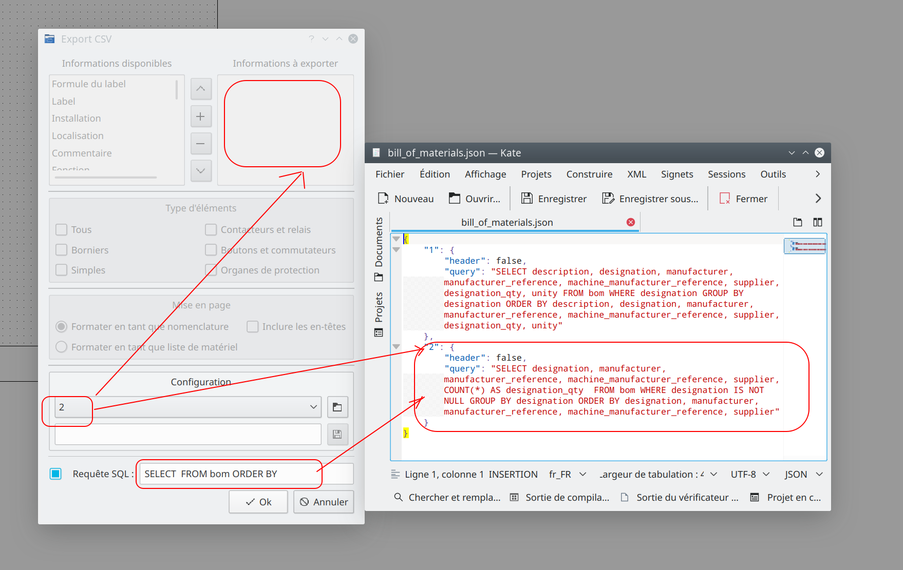
3,683 2019-11-20 15:55:53
Re: report de folio (1 replies, posted in FR : Aide, suggestions, discussions, ...)
Bonjour,
il suffit de faire un click droit dans le widget, là tu as plusieurs options, voir les reports libres, lier ce report.
3,684 2019-11-19 16:14:34
Re: Discussion sur l'export CSV (58 replies, posted in FR : Aide, suggestions, discussions, ...)
quantity =1
designation_qty =4
3,685 2019-11-19 14:17:50
Re: Discussion sur l'export CSV (58 replies, posted in FR : Aide, suggestions, discussions, ...)
C'est une liste de matériel, c'est donc normal s'il trouve 4 références identiques qu'il ne crée qu'une ligne avec ta référence et comptabilise le nombre total dans le champ "quantity".
m_format_as_bom_rb = liste de materiel
Maintenant examine la requête SQl, en dur dans le code, ça devrait être plus clair pour toi, ou pas. ![]()
QString where_bom;
    if(ui->m_format_as_bom_rb->isChecked())
    {
        if (where.isEmpty()) {
            where = " WHERE designation IS NOT NULL";
        } else {
            where.append(" AND designation IS NOT NULL");
        }

    }

    QString group_by = ui->m_format_as_bom_rb->isChecked() ? " GROUP BY designation" : "";
    QString q(select + column + count + from + where + where_bom + group_by + order_by);
    return q;
3,686 2019-11-19 12:14:02
Re: How to split device (not relay or terminals) to few parts? (4 replies, posted in EN : Help, suggestions, discussions, ...)
3,687 2019-11-19 10:56:40
Re: Discussion sur l'export CSV (58 replies, posted in FR : Aide, suggestions, discussions, ...)
Galexis wrote:
J'ai un soucis avec l'export csv en mode liste de matériel : il ne comptabilise pas le nombre d'élément de référence identique.
J'ai 4 relais de référence identique, dans la liste la référence apparaît sur une seule ligne et indique une quantité de 4.
La requête sqlite me parait pourtant pas mal....
Je ne vois pas ce qui cloche ..la référence apparaît sur une seule ligne et indique bien une quantité de 4..
3,688 2019-11-19 10:08:45
Re: Orientation cartouche (3 replies, posted in FR : Aide, suggestions, discussions, ...)
rallyedescartes wrote:
Ah oui personnellement je trouve pratique de pouvoir relier un element à un conducteur. Je ne pense pas que cela soit possible actuellement. Pouvez-vous me confirmer?
Justement on relie impérativement les bornes des éléments entre eux par des conducteurs, qui eux ont des propriétés électriques, d'équipotentialité, etc.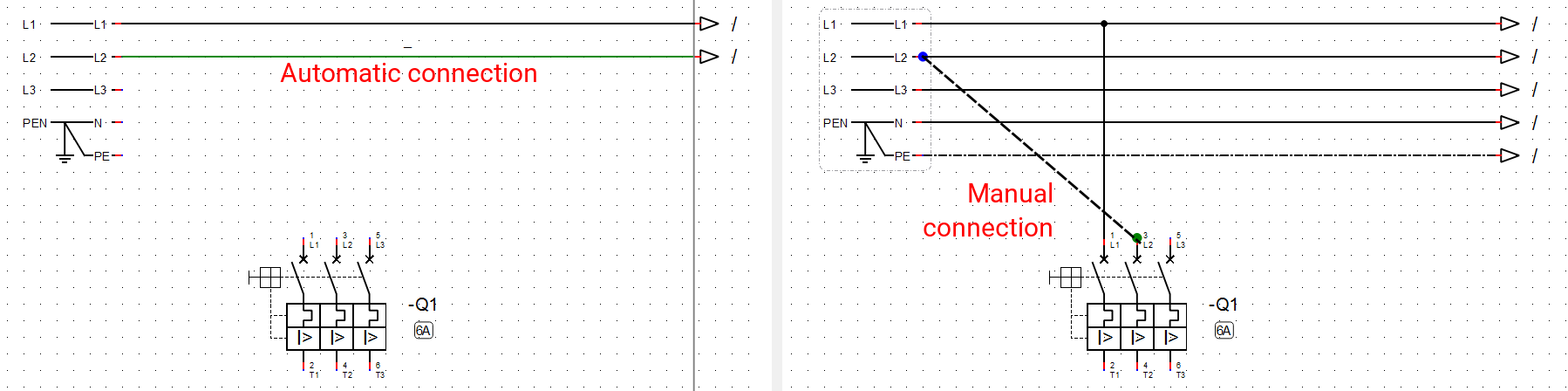
Les outils formes et traits "basic shapes" sont là pour dessiner une liaison mécanique, délimiter une zone, un coffret ou pour faire de petits dessins, en aucune façon il ne faut s'en servir pour relier des éléments. Autant faire ses schémas sous Paint ou Excel ... ![]()
rallyedescartes wrote:
Pouvoir directement éditer un élément en lecture seule. Au lieu de l'enregister sous dans notre collection puis de le modifier. C'est juste pas très intuitif actuellement.
Editer une image en pouvant paramétrer la longueur et la largeur séparemment.
Ce sont des avis personnels. Etant nouveau dans ce domaine je suis sur qu'il existe de bonnes raisons expliquant pourquoi tel ou tel retours d'utilisateur n'est pas possible/une bonne idée.
La collection officielle sera écrasée lors des mise à jour du logiciel, pas la collection utilisateur, voila pourquoi on là force en lecture seule.
Un symbole peut-être édité online suffit de le drag and drop sur le schéma, la modification pourra cohabiter avec la version précédente ou remplacer ce même symbole dans tout ton schéma après une réouverture de ton projet.
Quelques exemples de schémas réalisés sous QET :
https://download.qelectrotech.org/qet/schemas_pdf/
3,689 2019-11-19 09:55:11
Re: Orientation cartouche (3 replies, posted in FR : Aide, suggestions, discussions, ...)
rallyedescartes wrote:
Bonjour
Bonjour
rallyedescartes wrote:
Je suis actuellement en école d'ingénieur et je viens de découvrir votre logiciel. Je compte m'en servir pour mon stage de fin d'étude. Je dois editer des shémas pour des installations de panneaux solaires en Afrique du sud. Tout d'abord félicatations. Je ne suis pas encore très habitué avec les cad en electricité pourtant la prise en main est plutot facile.
J'aurais deux trois questions dont la premiere concerne les cartouches. Sur ma mise en forme je souhaiterais les placer à droite. Mon problème est que l'écriture est verticale. Il y a t il un moyen de changer l'orientation de l'écriture dans les cartouches ?
Non. Les cartouches à droites sont prévus pour être imprimés dans du A3, Le texte est horizontal dans le cartouche.
rallyedescartes wrote:
Ensuite et c'est plus une question d'ordre générale. Peut on faire des recherches de topic ? Par exemple je souhaitais vérifier si il n'y avait pas déjà eu cette question.
Sur le forum tu as deux boutons, search recherche par défaut depuis le moteur du forum, certes limité, et GG_search instance de Recherche personnalisée Google, après il y a la documentation online, ainsi que la chaîne Youtube, etc.
rallyedescartes wrote:
Enfin pour mes premiers retour utilisateur. Le fait de pouvoir adapter l'echelle des symbols sans passer par l'éditeur serait vraiment un plus je pense.
Le scale des symboles est fonction de la dimension de ton diagramme plus tu augmentes le nombres de colonnes, lignes, plus les symboles apparaitront petits. Et vice versa.
rallyedescartes wrote:
De plus pouvoir personnaliser ses propres raccourcis serait top. Enfin editer plusieurs conducteurs en meme temps serait un vrai plus. Par erreur je n'avais pas bien configuré mon SLD jái pris pas mal de temps à éditer les propriétés de mes conducteurs. Apres ca reste une erreur de ma part au début.
Encore bravo pour votre travail et bonne continuation.
ps: Il y a t il un moyen de vous soutenir/aider autrement que par un don ? Etudiant ne roulant pas sur l'or. Quelques euros ne vont pas me ruiner mais si je peux faire plus je vous invite à me dire comment.
Çà dépend du temps de libre que tu as à disposition ainsi que de tes connaissances, programmation C++/Qt, travailler sur la documentation (Sphinx), etc. Nous avons aussi synchronisé et externalisés nos sources sur Github, il est ainsi plus simple de participer et de faire une Pull request que la procedure normale pour rejoindre le projet > https://qelectrotech.org/wiki_new/doc/rejoin_project
3,690 2019-11-17 16:26:47
Topic: Linux compile with Qt online versions (14 replies, posted in Code)
Get Qt 5 and install the version you want in your $HOME Qt directory:
wget http://download.qt.io/official_releases/online_installers/qt-unified-linux-x64-online.runEdit qtchooser/qt5.conf
cat /usr/lib/x86_64-linux-gnu/qtchooser/qt5.conf
/home/laurent/Qt/5.13.2/gcc_64/bin
/home/laurent//Qt/5.13.2/gcc_64/lib
cat .bashrc
PATH=.:~/Qt/5.13.2/gcc_64/bin:$PATH
export PATH=~/kde/src/kdesrc-build:$PATH
Apply change
source ~/.bashrc $ qtchooser -print-env
QT_SELECT="default"
QTTOOLDIR="/home/laurent/Qt/5.13.2/gcc_64/bin"
QTLIBDIR="/home/laurent/Qt/5.13.2/gcc_64/lib"$ qmake --version
QMake version 3.1
Using Qt version 5.13.2 in /home/laurent/Qt/5.13.2/gcc_64/libhttps://community.kde.org/Get_Involved/ … esrc-build
https://jbbgameich.github.io/misc/2019/ … om-qt.html
mkdir -p ~/kde/src
cd ~/kde/src/
git clone https://invent.kde.org/sdk/kdesrc-build.git  && cd kdesrc-build
Edit ~/.kdesrc-buildrc, and replace the path to Qt qtdir with the path you installed Qt to. The line should then look similar to this:
cat .kdesrc-buildrc
# This is a sample kdesrc-build configuration file appropriate for KDE
# Frameworks 5-based build environments.
#
# See the kdesrc-buildrc-sample for explanations of what the options do, or
# view the manpage or kdesrc-build documentation at
# https://docs.kde.org/trunk5/en/extragea … index.html
global
branch-group kf5-qt5
kdedir ~/kde # Where to install KF5-based software
# Uncomment this and edit value to choose a different Qt5
qtdir ~/Qt/5.13.2/gcc_64 # Where to find Qt5# Where to download source code. By default the build directory and
# logs will be kept under this directory as well.
source-dir ~/kde
end global# Instead of specifying modules here, the current best practice is to refer to
# KF5 module lists maintained with kdesrc-build by the KF5 developers. As new
# modules are added or modified, the kdesrc-build KF5 module list is altered to
# suit, and when you update kdesrc-build you will automatically pick up the
# needed changes.# NOTE: You MUST change the path below to include the actual path to your
# kdesrc-build installation.
include ~/kde/src/kdesrc-build/kf5-qt5-build-include# If you wish to maintain the module list yourself that is possible, simply
# look at the files pointed to above and use the "module-set" declarations that
# they use, with your own changes.# It is possible to change the options for modules loaded from the file
# included above (since it's not possible to add a module that's already been
# included), e.g.
options kcoreaddons
make-options -j16
end options
Compiling KDE frameworks :
kdesrc-build kwidgetsaddons karchive kcoreaddons --include-dependencies
cp ~/kde/mkspecs/*.pri ~/Qt/5.13.2/gcc_64/mkspecs/modules/
Get QET source files and compile it:
git clone git://git.tuxfamily.org/gitroot/qet/qet.git qet_git
cd qet_git
mkdir build/ && cd build
qmake ../qelectrotech.pro
make -j$(nproc)
3,691 2019-11-16 14:18:50
Re: feature set xref slave position (29 replies, posted in Code)
Hi,
added, thanks Stromie.
3,692 2019-11-10 22:20:25
Re: Discussion sur l'export CSV (58 replies, posted in FR : Aide, suggestions, discussions, ...)
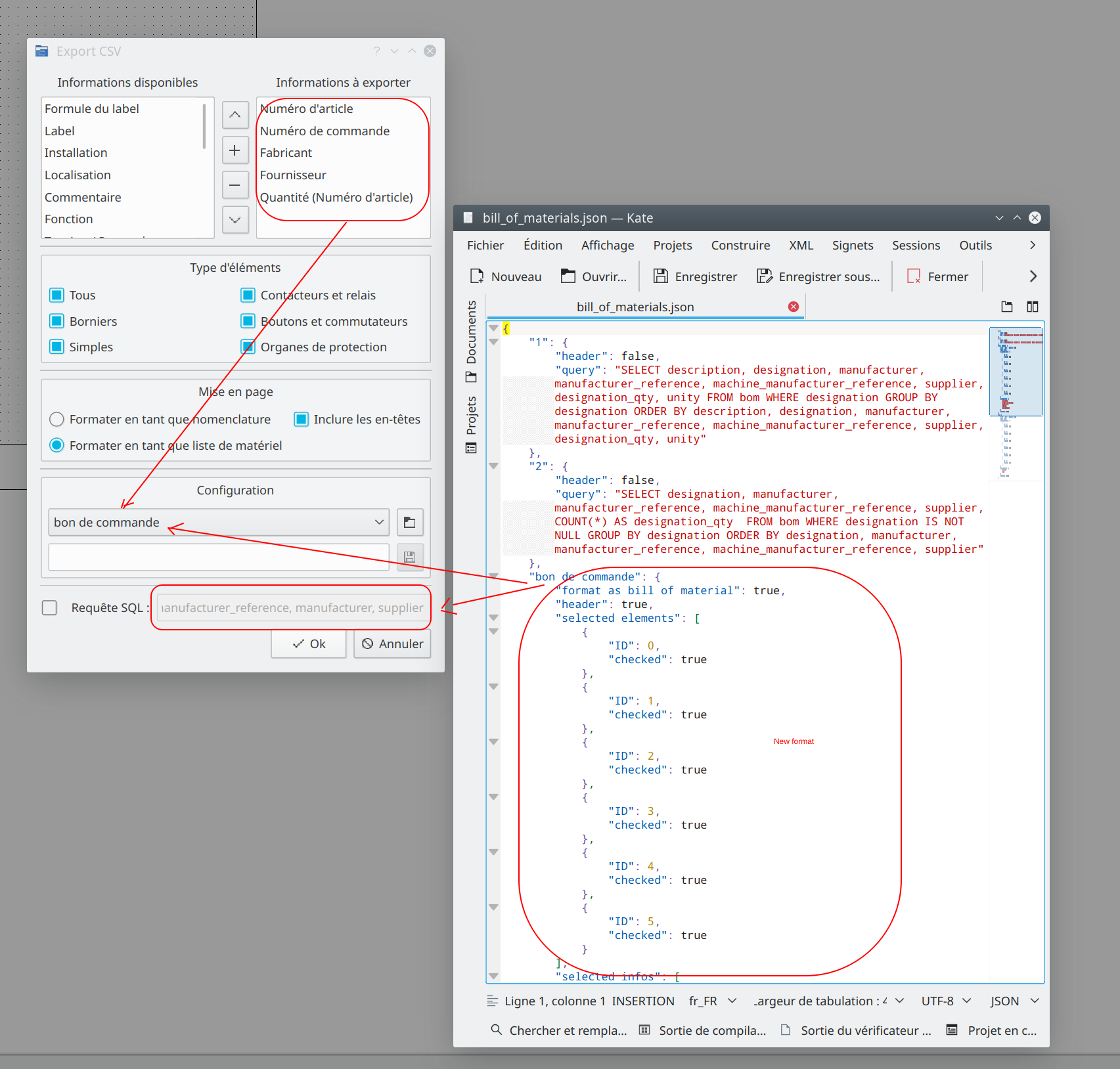
Nouvelle interface :
https://git.tuxfamily.org/qet/qet.git/c … 17c6014dd9
On peut maintenant choisir plusieurs listes à exporter, mais il manque encore l'export en lot des fichiers "nomenclature_%(project(title))_%(type)*.csv.
Çà me parait utile, exporter en une seule opération les différents fichiers CSV pour les imprimantes :la liste des étiquettes spéciales pour les boutons/commutateurs, la liste pour les contacteurs avec étiquettes blanches, les disjoncteurs avec étiquettes jaunes par exemple, etc. Vous en pensez quoi?
3,693 2019-11-10 20:04:37
Re: Présentation c'est par ici. (130 replies, posted in Bar Fourre-tout)
Salut Didier,
bah c'est déjà pas mal, ^^ j'ai par contre une dizaine de fichiers écrits du temps de PHP 5.X qui ne passent plus si version PHP 7.3... Ce n'est pas important, ça ne concerne que le Viewer des éléments elmt (des collections) -> SVG online -> https://qelectrotech.org/forum/viewtopi … 812#p10812
3,694 2019-11-10 16:39:43
Re: Discussion sur l'export CSV (58 replies, posted in FR : Aide, suggestions, discussions, ...)
Niet ![]() , on ne vas pas lister les basic shapes dans l'export, mais tu peux faire comme Nuri et ses éléments fantômes (symboles blanc sur fond blanc).
, on ne vas pas lister les basic shapes dans l'export, mais tu peux faire comme Nuri et ses éléments fantômes (symboles blanc sur fond blanc).
3,695 2019-11-10 16:35:35
Re: Présentation c'est par ici. (130 replies, posted in Bar Fourre-tout)
Bonjour Didier, tu es le bienvenu ici.
Bon je vois que tu as du pain sur la planche avec ton bateau, les moteurs fonctionnent c'est déjà bien. De quoi occuper les journées d'un jeune retraité, veinard ... me reste encore dix ans à s/purger/tenir/ .... ![]()
didier wrote:
et j'ai passé 35 ans dans l'informatique.
L'informatique c'est un vaste domaine, si tu es à l'aise dans un langage de programmation, tu pourrais toi aussi apporter ta pierre à l’édifice et rejoindre l’équipe, s'il te reste un peu de temps libre, bien sur. ![]()
@+
Laurent
3,696 2019-11-09 16:56:06
Re: Discussion sur l'export CSV (58 replies, posted in FR : Aide, suggestions, discussions, ...)
galexis wrote:
J'ai une question: A priori c'est une base SQLITE. Où est-elle stockée ? Dans le projet ou dans QET ? Momentanée ou permanente ?
.
Si tu veux faire des tests de requêtes SQL, tu as ce petit patch, il passe la bdd SQLITE sur ton disque et l'enregistre dans le répertoire home de QET, la bdd sera supprimée chaque fois que tu lanceras une nouvelle requête dans le widget.
Comme c'est moins rapide sur de gros projet qu'en RAM, je n'enverrai surement pas ce patch.
--- sources/ui/bomexportdialog.cpp
+++ sources/ui/bomexportdialog.cpp
@@ -320,8 +320,11 @@ QString BOMExportDialog::headers() const
  */
 bool BOMExportDialog::createDataBase()
 {
-        //Create a sqlite data base to sort the bom
+        //Delete previous sqlite database
+    QFile::remove(QETApp::configDir() + "/bill_of_material.sqlite");
+        //Create a sqlite database to sort the bom
     m_data_base = QSqlDatabase::addDatabase("QSQLITE", "bill_of_material");
+    m_data_base.setDatabaseName(QETApp::configDir() + "/bill_of_material.sqlite");
     if (!m_data_base.open())
     {
         m_data_base.close();
3,697 2019-11-08 21:15:25
Re: Affichage panneau bibliothèque et projets (4 replies, posted in FR : Aide, suggestions, discussions, ...)
@Erik,
si Galexis laisse l'interface par défaut, c'est sur que même sur un écran 27" UHD il aura très peu de place pour dessiner, suffit d'empiler les widgets dans le dock.
Cordialement,
Laurent
3,698 2019-11-08 21:11:52
Re: Discussion sur l'export CSV (58 replies, posted in FR : Aide, suggestions, discussions, ...)
Joshua wrote:
Expliquer comment est composé la bdd oui, après expliqué comment composer une requête c'est plus difficile, SQL est un langage. Après on peut mettre 4/5 exemples qui peuvent être utile dans notre cas.
Ou un lien HTML vers la doc ...
3,699 2019-11-08 20:04:38
Re: Manuel de la version 07 en pdf ? (3 replies, posted in Documentation)
git clone https://github.com/qelectrotech/qelectrotech-doc.git
cd qelectrotech-doc.git/
cd source/
for i in `find -type f`; do mv "$i" "$(echo $i | tr A-Z a-z)"; done
cd ..
rm -Rf build/
make latex
make latexpdf