Hi everyone,
Here's a couple of elements I have recently made.
You are not logged in. Please login or register.
QElectroTech → Posts by bat
Hi everyone,
Here's a couple of elements I have recently made.
Hi mate
It depends which features it has, let's assume you have a schneider electric switch, well then you can simply look on the side of your component and easily copy the element. Otherwise you will have to do it from scratch.
Salut Nardo
Saisie le texte en maintenant L CTRL et le clic gauche de ta souris, normalement tu pourras rendre tes repères plus clairs
Hi mate, I will always make elements I made available for my professional and personal projects, I have also a strong interest to draw elements in my free time, especially PLC's and other Misc elements. However, it is always a challenge to properly draw each element and make sure they are properly drawn and updated to the latest standards.
With that said, is there any document available online describing the way to properly draw PLC's? Right dimensions, separation between each I/O etc...
Salut,
Tu dois cocher imprimer les bornes mais si tu ne souhaites pas les voir, imprime en noir et blanc.
Tu peux également éditer tes symboles concernés et ajouter des traits en dessous les bornes dans ce cas, même en ne cochant pas la case "imprimer les bornes" tu n'auras plus de trous !
Hi mate, if i understood your issue properly, you should be able to set the proper designation of the text in the element editor, do not use user text, you should use 'element information' and under it, select the proper usage, it can be label, location etc.. whatever you need.
I hope i helped
Hello
I think you may be able to solve your issue by selecting the tick box for "Show one text per folio potential"
This is located only in the Project Properties -> New Folio -> Conductor -> Type -> Multiline
It's very similar to the screen you show just with this one addition. This way for all conductors you'll only get the 1 wire number shown in each folio. (I'm not sure off the top of my head if this can be applied retrospectively or only takes effect when you make the next new folio)
Hope this helps
I don't think it's a good solution for him, tho it's a great way to fix over lapping labels.
Usually, what I do, i just stack both labels together, it will make no difference, if I don't need to use terminal blocks & alot of folio carryovers, i'll just manually add the labels using text rather than use the built-in function to label my conductors.
I don't see your PR here.. https://github.com/qelectrotech/qelectr … rror/pulls
Should be all good now !
Nice. ;-)
PR done, I have also added a couple more stuff !
hi mate, for now you'll have to stick to current workarounds but perhaps in the future, we'll see this feature added !
I believe it probably is a bug, i've had it happen to me pretty much every time I make an element, it's not a big deal tho
Hello Bat,
maybe you can make a Github PR to add these elements
directly on "elements/10_electric/20_manufacturers_articles/johnson_controls"
Will do ![]()
Hi everybody,
I have recently used a huge array of elements I had to make for my projects, i'm sharing some of those.
Hi mate, you may need to create a custom format that includes both "plant" and the sequential number. Make sure to watch the naming configuration, there may be a mistake. Double check your data input it may not be assigned properly.
Bonjour à tous,
Je vous sollicicte car je n'arrive pas à réaliser un plan d'implantation propre, je trouve que ça fait brouillon.
Comment faites vous? Le cas echeant, Connaissez vous d'autre logiciel gratuit pour ce faire ?
Merci par avance de vos réponses.Bonne journee
Salut, je te conseille de suivre des guides d'électriciens sur Youtube, tu peux aussi tenter de chercher sur internet mais si tu sais ce que tu dois faire une petite vidéo Youtube fera l'affaire.
Dans le cas où tu es un artisan lambda, je te conseille de chercher des cours en ligne et également de lire la norme NFC 15-100.
Hi mate
There little to no network elements currently in the librairy however, you can easily draw your own and if you wish, you can also share the drawn elements with the community.
Hello,
I apologise for the delayed reply.
Here are the relevant symbols which were corrected.
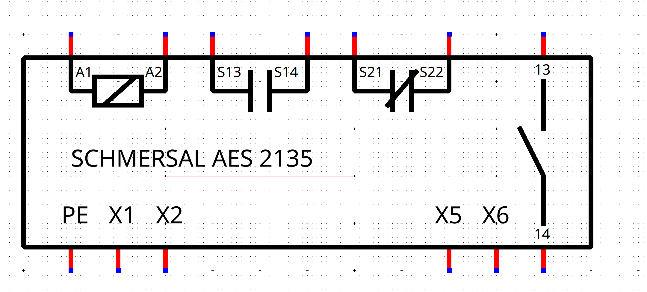
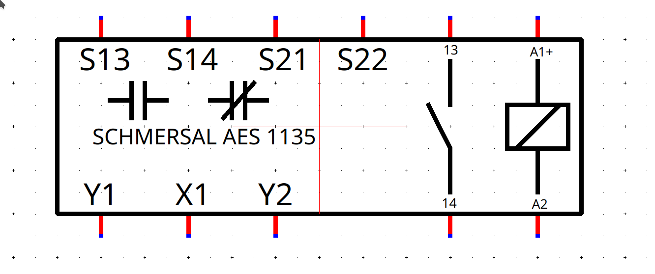
Secure relay 2135

Here's a few SCHMERSAL symbols i made !
Feel free to correct me if you spot any mistake.

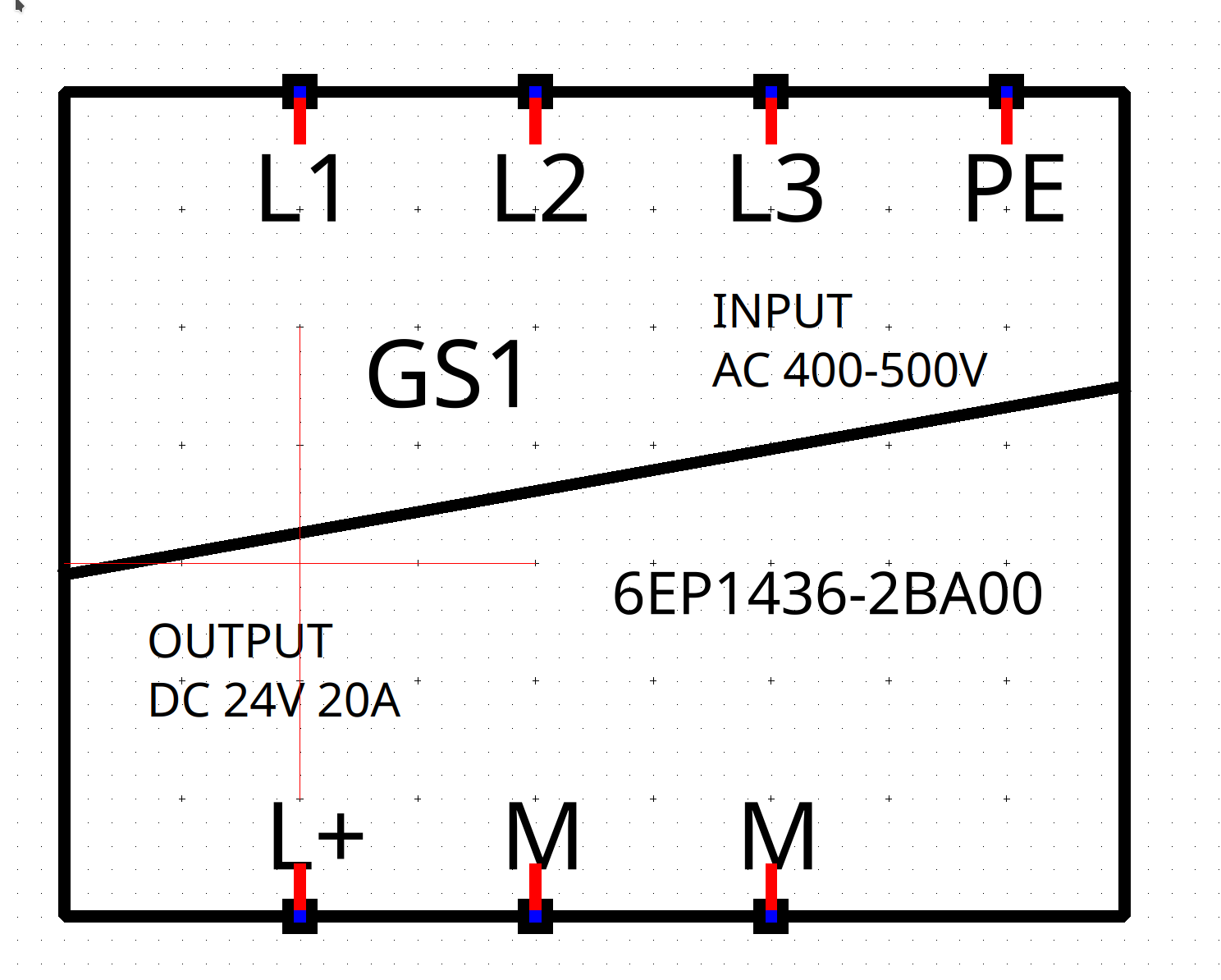
6EP1436-2BA00 Siemens powersupply![]()

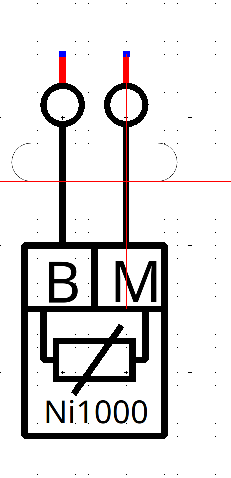
Siemens Ni1000 temperature probe![]()

Sorry for my English, I used google translate.
Good morning,
Here is the trick I use to have 2 labels on 1 conductor.
I duplicate 1 of the elements (I put it in backward: important) and I superimpose it on the 1st.
Pay attention to the position of the element (Front or backward) because if you connect 1 new conductor (it always connects to the element most in front / to be confirmed), it may not be connected to the right element, and this will cause problems if you delete the duplicated element (folio reference/terminal blocks, etc.) as well as in the management of terminal blocks or others (2 elements to be managed instead of just 1): on the attached diagram I have separated the 2 elements at the bottom of the page to display the result.
(I have attached 1 project with explanations)
The advantage of my trick is that if the conductor label changes, I can apply it to all the labels linked together, whereas if I had put a text field, it must be modified manually.There may be more simple, here is my trick.
Thanks for sharing the tips mate ![]()
QElectroTech → Posts by bat
Powered by PunBB, supported by Informer Technologies, Inc.
Generated in 0.020 seconds (63% PHP - 37% DB) with 6 queries