You are not logged in. Please login or register.
Active topics Unanswered topics
Search options (Page 96 of 305)
Hi Simon,
Yes I read it, but didn't have time to look.
I had to reply to other more important emails.
I resumed my work following a sick leave of 2 months because of a big burn out and other health problem.
When I leave work I am exhausted and not always have the time or strength to address these issues.
WoW ;-)
What a pleasant surprise this morning when I opened my mailbox...
It is the world's most populous country, with a population of more than 1.4 billion.
Good morning,
I have recently discovered your project and like to introduce this to my
workmates as an alternative to the currently used software to do our
electrical drawings (which costs us money and has some flaws,
unfortunately).
Given the fact that our guys are mostly Chinese and would rather like to use
a GUI in their language, I'd like to ask about the possibility to add a
Chinese translation to the software.
Is there a process already going on? If not, do you think I could contribute
to your project in that way or isn't it on your roadmap?
I'd be glad to hear your opinion about this!
Best regards from Zhongshan (near Hongkong),
Stephan
Hi Simon,
for now, I saw no support for Qt6.x on MXE cross-compile for Windows,
https://github.com/mxe/mxe/issues/2594
No Debian maintainers for Qt 6.x and no volunteers to package it yet.
https://lists.qt-project.org/pipermail/ … 40110.html
https://www.phoronix.com/scan.php?page= … aintainers
About KF5 to KF6 only KCoreAddons seem compatible for now
https://www.volkerkrause.eu/2021/12/11/ … t-qt6.html
Nothing is ready yet.
I think 0.9 wil be released when Joshua was finish new terminal block, but the road is long.
13:16:18.851 Info: "QElectroTech V 0.90-DEV~d932f8ea.snap"
13:16:18.851 Info: "Compilation : GCC 9.3.0"
13:16:18.852 Info: "Built with Qt 5.15.3 - Date : Jan  5 2022 : 11:05:49"
13:16:18.852 Info: "Run with Qt 5.15.3 using 8 thread(s)"
13:16:18.852 Info: "CPU : model name\t: Intel(R) Core(TM) i7-8550U CPU @ 1.80GHz\n"
13:16:18.852 Info: "RAM Total : 15828 MB"
13:16:18.852 Info: "RAM Available : 12145 MB"
13:16:18.852 Info: "GPU : "
13:16:18.852 Info: "GPU RAM : @ToDo"
13:16:18.852 Info: "OS : linux  - x86_64 - Version : Ubuntu Core 20 - Kernel : 5.4.0-90-generic"
13:16:18.852 Info: *** Qt screens ***
13:16:18.852 Info: "( 1 : 3840 x 2160 )"
13:16:19.142 Info: Elements collection reload
13:16:19.164 Info: Elements collection finished to be loaded
13:53:59.488 Info: Start-up
13:53:59.526 Info: debugging enabled: false
13:53:59.526 Info: Qt library version: 5.15.3
13:53:59.526 Info: Qt library location default prefix: "/usr"
13:53:59.527 Info: Qt library location documentation: "/usr/share/qt5/doc"
13:53:59.527 Info: Qt library location headers: "/usr/include/x86_64-linux-gnu/qt5"
13:53:59.527 Info: Qt library location libraries: "/usr/lib/x86_64-linux-gnu"
13:53:59.527 Info: Qt library location executables: "/usr/lib/x86_64-linux-gnu/qt5/libexec"
13:53:59.527 Info: Qt library location Qt binaries: "/usr/lib/qt5/bin"
13:53:59.527 Info: Qt library location Qt plugins: "/usr/lib/x86_64-linux-gnu/qt5/plugins"
13:53:59.527 Info: Qt library location installed QML extensions: "/usr/lib/x86_64-linux-gnu/qt5/imports"
13:53:59.527 Info: Qt library location installed QML extensions: "/usr/lib/x86_64-linux-gnu/qt5/qml"
13:53:59.527 Info: Qt library location dependent Qt data: "/usr/lib/x86_64-linux-gnu/qt5"
13:53:59.527 Info: Qt library location independent Qt data: "/usr/share/qt5"
13:53:59.527 Info: Qt library location translation: "/usr/share/qt5/translations"
13:53:59.527 Info: Qt library location examples: "/usr/lib/x86_64-linux-gnu/qt5/examples"
13:53:59.527 Info: Qt library location Qt testcases: "/usr/tests"
13:53:59.527 Info: Qt library location Qt settings: "/etc/xdg"
13:53:59.527 Info: "GitRevision d932f8ea01963f8f505714835f2ee24d029ef5fb"
13:53:59.527 Info: "QElectroTech V 0.90-DEV~d932f8ea.snap"
13:53:59.528 Info: "Compilation : GCC 9.3.0"
13:53:59.528 Info: "Built with Qt 5.15.3 - Date : Jan  5 2022 : 11:05:49"
13:53:59.528 Info: "Run with Qt 5.15.3 using 8 thread(s)"
13:53:59.528 Info: "CPU : model name\t: Intel(R) Core(TM) i7-8550U CPU @ 1.80GHz\n"
13:53:59.528 Info: "RAM Total : 15828 MB"
13:53:59.528 Info: "RAM Available : 12445 MB"
13:53:59.528 Info: "GPU : "
13:53:59.528 Info: "GPU RAM : @ToDo"
13:53:59.528 Info: "OS : linux  - x86_64 - Version : Ubuntu Core 20 - Kernel : 5.4.0-90-generic"
13:53:59.528 Info: *** Qt screens ***
13:53:59.528 Info: "( 1 : 3840 x 2160 )"
13:53:59.817 Info: Elements collection reload
13:53:59.838 Info: Elements collection finished to be loaded
13:59:05.122 Info: Start-up
13:59:05.161 Info: debugging enabled: false
13:59:05.161 Info: Qt library version: 5.15.3
13:59:05.161 Info: Qt library location default prefix: "/usr"
13:59:05.161 Info: Qt library location documentation: "/usr/share/qt5/doc"
13:59:05.161 Info: Qt library location headers: "/usr/include/x86_64-linux-gnu/qt5"
13:59:05.161 Info: Qt library location libraries: "/usr/lib/x86_64-linux-gnu"
13:59:05.161 Info: Qt library location executables: "/usr/lib/x86_64-linux-gnu/qt5/libexec"
13:59:05.162 Info: Qt library location Qt binaries: "/usr/lib/qt5/bin"
13:59:05.162 Info: Qt library location Qt plugins: "/usr/lib/x86_64-linux-gnu/qt5/plugins"
13:59:05.162 Info: Qt library location installed QML extensions: "/usr/lib/x86_64-linux-gnu/qt5/imports"
13:59:05.162 Info: Qt library location installed QML extensions: "/usr/lib/x86_64-linux-gnu/qt5/qml"
13:59:05.162 Info: Qt library location dependent Qt data: "/usr/lib/x86_64-linux-gnu/qt5"
13:59:05.162 Info: Qt library location independent Qt data: "/usr/share/qt5"
13:59:05.162 Info: Qt library location translation: "/usr/share/qt5/translations"
13:59:05.162 Info: Qt library location examples: "/usr/lib/x86_64-linux-gnu/qt5/examples"
13:59:05.162 Info: Qt library location Qt testcases: "/usr/tests"
13:59:05.162 Info: Qt library location Qt settings: "/etc/xdg"
13:59:05.162 Info: "GitRevision d932f8ea01963f8f505714835f2ee24d029ef5fb"
13:59:05.162 Info: "QElectroTech V 0.90-DEV~d932f8ea.snap"
13:59:05.162 Info: "Compilation: GCC 9.3.0"
13:59:05.162 Info: "Built with Qt 5.15.3 - Date : Jan  5 2022 : 11:05:49"
13:59:05.162 Info: "Run with Qt 5.15.3 using 8 thread(s)"
13:59:05.162 Info: "CPU : model name\t: Intel(R) Core(TM) i7-8550U CPU @ 1.80GHz\n"
13:59:05.162 Info: "RAM Total : 15828 MB"
13:59:05.162 Info: "RAM Available : 12407 MB"
13:59:05.162 Info: "GPU : "
13:59:05.162 Info: "GPU RAM : @ToDo"
13:59:05.162 Info: "OS : linux  - x86_64 - Version : Ubuntu Core 20 - Kernel : 5.4.0-90-generic"
13:59:05.162 Info: *** Qt screens ***
13:59:05.162 Info: "( 1 : 3840 x 2160 )"
13:59:05.473 Info: Elements collection reload
13:59:05.826 Info: Elements collection finished to be loaded
13:59:05.473 Info: Elements collection reload
13:59:05.826 Info: Elements collection finished to be loaded
~8 000 Elements in collection loaded in 0.353 seconds
If you don't have common collection with Snap repository on QET 0.9-dev.
Edit file
~/snap/qelectrotech/current/.config/QElectroTech/
Change common-collection-path=defaut to /snap/qelectrotech/current/usr/local/share/qelectrotech/elements/
[elements-collections]
common-collection-path=/snap/qelectrotech/current/usr/local/share/qelectrotech/elements/
custom-collection-path=default
custom-tbt-path=default
S'il en manque ou que tu en crée de nouveaux n'hésites pas à nous les envoyer.
https://flathub.org/apps/details/org.qe … lectroTech
Additional information
Updated
January 6, 2022
Version
0.8.0
Tu as le choix, j'en avais crée pas mal de symboles à l'époque pour mes schémas :
[15:09:44] laurent@debian:~/Qet-svn/git/qet/elements/10_electric/10_allpole/450_high_voltage$ tree
.
├── appareil_ferme_cle_prisonniere.elmt
├── appareil_ouvert_cle_prisonniere.elmt
├── cle_absente_pene_rentree_manoeuvre_libre.elmt
├── cle_absente_pene_sorti.elmt
├── cle_libre_pene_rentree_manoeuvre_libre.elmt
├── cle_libre_pene_sorti.elmt
├── cle_prisioniere_pene_rentree_manoeuvre_libre.elmt
├── cle_prisionniere_pene_rentree_manoeuvre_bloquee.elmt
├── contacteur_crm.elmt
├── contacteur_f_crm.elmt
├── disj_debrochable_dm1-w.elmt
├── disj_debrochable_dm1-z.elmt
├── disjoncteur_dm1-a.elmt
├── disjoncteur_dm1-d.elmt
├── disjoncteur_dm1-s.elmt
├── disjoncteur_dm2.elmt
├── eclateur_double.elmt
├── eclateur_simple.elmt
├── element_flexible.elmt
├── hvpole.elmt
├── interrupteur_imb.elmt
├── interrupteur_imc.elmt
├── interrupteur_im.elmt
├── interrupteur_pm.elmt
├── interrupteur_qmb.elmt
├── interrupteur_qmc.elmt
├── interrupteur_qm.elmt
├── interrupteur_sectionneur_de_terre.elmt
├── ligne_aerienne.elmt
├── ligne_immergee.elmt
├── ligne_souterraine.elmt
├── ligne_triphase_2.elmt
├── ligne_triphase.elmt
├── qet_directory
├── serrure_cle_tjs_libre.elmt
├── serrure_cle_tjs_prisionniere.elmt
├── signal_capacitif.elmt
└── transf_cm.elmt
0 directories, 38 files
Renew qelectrotech.org domain for 5 years 93,96 EUR (It costs much less than paying annually).
Send 400€ to Joshua to motivate him to continue the hard work on the new terminal block generator ^^.
Thanks for your support. 
S.DEFFAUX wrote:Bonjour je pense qu'il serait utile de rajouter un onglet "Ouvrir Example"
Bonne idée, mais tres compliqué à mettre en place.
Les chemin d’accès selon le système d'exploitation, le paquage seront très différents, exemple:
Paquets Linux Debian, Ubuntu, etc
/usr/share/qelectrotech/examples
Flatpak
/var/lib/flatpak/app/org.qelectrotech.QElectroTech/current/active/files/share/qelectrotech/examples
Snap
/snap/qelectrotech/current/usr/local/share/qelectrotech/examples/
Linux Compile
/usr/local/share/qelectrotech/examples
Windows installer
C:\Program Files\QElectroTech\examples
MacOS
Il n'est pas installé automatiquement par le bundle, il faut prendre le dossier examples apres montage du bundle et le copier sur le bureau par exemple.
09:50:35.855 Info: "QElectroTech V 0.90-DEV+d932f8ea0"
09:50:35.855 Info: "Compilation: GCC 10.2.0"
09:50:35.855 Info: "Built with Qt 5.15.3 - Date : Jan  5 2022 : 10:18:34"
09:50:35.855 Info: "Run with Qt 5.15.3 using 48 thread(s)"
09:50:35.855 Info: "CPU : model name\t: AMD Ryzen Threadripper 3960X 24-Core Processor\n"
09:50:35.855 Info: "RAM Total : 15640 MB"
09:50:35.855 Info: "RAM Available : 14490 MB"
09:50:35.856 Info: "GPU :  Red Hat, Inc. Virtio GPU (rev 01)\n"
09:50:35.856 Info: "GPU RAM : @ToDo"
09:50:35.856 Info: "OS : linux  - x86_64 - Version : KDE Flatpak runtime - Kernel : 5.10.0-10-amd64"
09:50:35.856 Info: *** Qt screens ***
09:50:35.856 Info: "( 1 : 1920 x 1200 )"
09:50:36.084 Info: Elements collection reload
09:50:36.642 Info: Elements collection finished to be loaded
~8 000 Elements in collection loaded in 0.558 s ...
Add fix for network printer on flathub QET stable (0.8)
https://github.com/flathub/org.qelectro … 29e2fdfb5f
If you don't have common collection with my Flatpak repository on QET 0.9-dev.
Edit file
~/.var/app/org.qelectrotech.QElectroTech/config/QElectroTech/QElectroTech.conf
Change common-collection-path=defaut to /app/share/qelectrotech/elements/
[elements-collections]
common-collection-path=/app/share/qelectrotech/elements/
custom-collection-path=default
custom-tbt-path=default
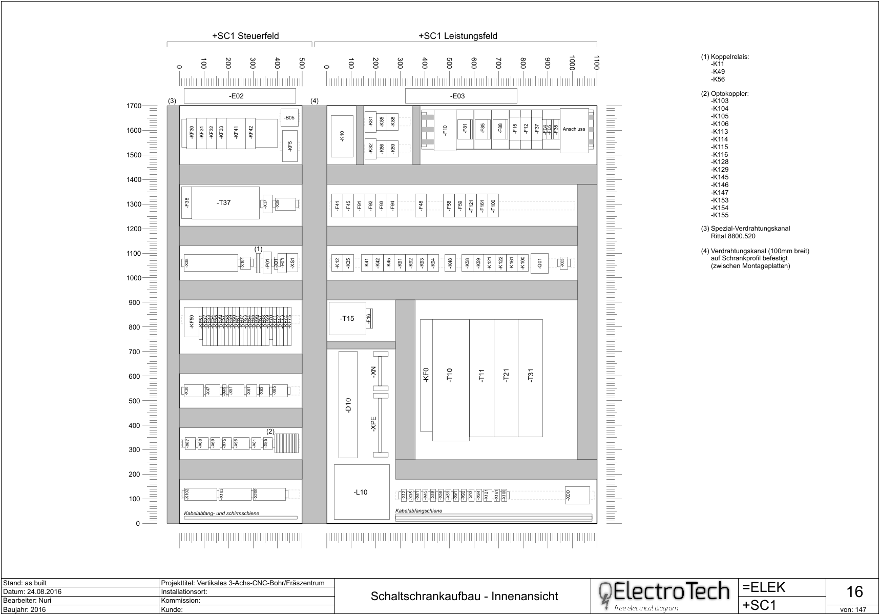
Nuri wrote:Pour faire les mise en armoire, je considère que 1 pixel = 1 mm. Ce qui signifie que la distance entre 2 points de la grille dans QET correspond en réalité à 1cm. Cela fait un folio beaucoup plus grand que ceux des schémas électriques et, pour cette raison, il faut créer un cartouche adapté à ces dimensions.
Quand tout est en place (folio de mise en armoire, cartouche approprié, vignettes du matériel électrique) c'est très rapide de faire une mise en armoire.
La plaque et les rails de montage ainsi que les goulottes de câblage sont réalisés avec des formes basiques (rectangles) pour pouvoir être facilement modifiés en fonction des besoins.
Au final, ca donne un plan qui ressemble à ca :
Exemple de mise en armoire
Aucune idée, te faudrait chercher dans les messages de Nuri, l'auteur, ou chercher cabinet.
Flatpak : add --socket=cups and --share=network
see :
https://github.com/flathub/org.libreoff … /issues/90
But error: Unknown socket type cups, valid types are: x11, wayland, pulseaudio, session-bus, system-bus, fallback-x11, ssh-auth
Fixed by upgrade Debian VM KVM to Bullseye.
Flatpak : add --socket=cups and --share=network
see :
https://github.com/flathub/org.libreoff … /issues/90
But error: Unknown socket type cups, valid types are: x11, wayland, pulseaudio, session-bus, system-bus, fallback-x11, ssh-auth
Fixed by upgrade Debian VM KVM to Bullseye.
Qelectrotech_nomenclature_Question
I am emailing in order to ask a question in regards to renaming nomenclature table headings.
For example, I created the following nomenclature table and I would like to rename the "Internal number" column to "Component ID".
Can you please let me know how I can add "Component ID" in the nomenclature list?
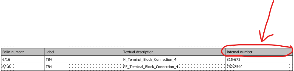
Joshua wrote:In the dialog where you define the nomenclature, setup what you want
and when it's done check the button 'SQL request' at the bottom of the
dialog, the line at right is now editable. According to your screenshot
the sql query should be something like this :
SELECT folio, label, description, machine_manufacturer_reference FROM
element_nomenclature_view WHERE ( element_type = 'Terminale' OR
element_type = 'Simple' OR element_sub_type = 'commutator' OR
element_sub_type = 'coil' OR element_sub_type = 'protection') ORDER BY
folio, label, description, machine_manufacturer_reference
Now append AS 'Component ID'just after the first
machine_manufacturer_reference
The begin of the sql query is now:
SELECT folio, label, description, machine_manufacturer_reference AS
'Component ID' FROM.............
Click OK.
In the same dialog you can save your current configuration to quickly
retrieve it for another project.
- Log -----------------------------------------------------------------
commit ae9faa2192b84c51869fde0ee5205c6115402f00
Author: joshua <Joshua@>
Date: Mon Jan 3 21:01:25 2022 +0100
Add toolbar widget for edit size of handler in diagram editor.
Add a combo box in the tool bar of diagram editor
to quickly change the size of the graphics handler item.
NOTE
only available for diagram editor, element editor will
come later.
https://twitter.com/rollapp/status/1473241119374860292
La version 0.7 est maintenant sur RollApp. Elle fonctionne dans un navigateur Web, pour ceux qui veulent essayer sur leur Ipad ou tablette Android.
https://www.rollapp.com/app/qelectrotech
La version 0.7 est maintenant sur RollApp.
scorpio810 wrote:https://git.tuxfamily.org/qet/qet.git/c … f509e23332
Checked changes on my HP elitebook 4K laptop + nvme ssd.
10:46:05.894 Info: Start-up
10:46:06.239 Info: "QElectroTech V 0.90-DEV+56685d0f3b0a58100c957a06d79751d3"
10:46:06.240 Info: "Compilation : GCC 9.3.0"
10:46:06.240 Info: "Built with Qt 5.15.2 - Date : Dec 18 2021 : 09:31:45"
10:46:06.241 Info: "Run with Qt 5.15.2 using 8 thread(s)"
10:46:06.241 Info: "CPU : NAME                                      \r\r\nINTEL(R) CORE(TM) I7-8550U CPU @ 1.80GHZ  \r\r\n\r\r\n"
10:46:06.241 Info: "RAM Total : 16199 MB"
10:46:06.242 Info: "RAM Available : 12333 MB"
10:46:06.242 Info: "GPU : VideoProcessor                \r\r\nIntel(R) UHD Graphics Family  \r\r\n\r\r\n"
10:46:06.242 Info: "GPU RAM : RAM Total : AdapterRAM  \r\r\n1073741824  \r\r\n\r\r\n B"
10:46:06.243 Info: "OS : winnt  - x86_64 - Version : Windows 10 Version 2009 - Kernel : 10.0.19044"
10:46:06.243 Info: *** Qt screens ***
10:46:06.244 Info: "( 1 : 3840 x 2160 )"
10:46:06.258 Info: Elements collection reload
10:46:07.731 Info: Elements collection finished to be load/ed
WOW under Windows ...... great improvement !!
10:46:06.258 Info: Elements collection reload
10:46:07.731 Info: Elements collection finished to be load/ed
Avec Joshua on a fait quelques petits tests, chacun de son coté, j'ai voulu confirmer ses dires: il faut mesurer le premier lancement après que Windows ai fini de ce lancer, les autres lancements seront 10 fois plus rapides donc non mesurables pour le test!
On prend par exemple la ReadyToUse 0.7 avec la même collection de la 0.9-dev soit ~ 7800 éléments, le chargement prend maxi 8 secondes à vu de nez.
On fait pareil avec la 0.8 ReadyToUse après le reboot de Windows et la même collection que la 0.9-dev ça donne environ 15 secondes ..
Pour information: la dernière 0.9-dev installer; elle ne prend maintenant que 2 secondes ... , donc on peut en conclure que MS à aussi fait de grosses améliorations de son coté sur les dernières maj de Windows 10 sur le lancement de certaines applications, il me semble que ça à toujours été plus près de la minute ... voir beaucoup plus chez certains ....
14:25:41.888 Info: "QElectroTech V 0.80c+87c957a06d79751d3"
14:25:41.888 Info: "Compilation : GCC 9.3.0"
14:25:41.888 Info: "Built with Qt 5.15.2 - Date : Feb 21 2021 : 10:29:35"
14:25:41.889 Info: "Run with Qt 5.15.2 using 8 thread(s)"
14:25:41.889 Info: "CPU : NAME                                      \r\r\nINTEL(R) CORE(TM) I7-8550U CPU @ 1.80GHZ  \r\r\n\r\r\n"
14:25:41.889 Info: "RAM Total : 16199 MB"
14:25:41.889 Info: "RAM Available : 12499 MB"
14:25:41.890 Info: "GPU : VideoProcessor                \r\r\nIntel(R) UHD Graphics Family  \r\r\n\r\r\n"
14:25:41.890 Info: "GPU RAM : RAM Total : AdapterRAM  \r\r\n1073741824  \r\r\n\r\r\n B"
14:25:41.890 Info: "OS : winnt  - x86_64 - Version : Windows 10 Version 2009 - Kernel : 10.0.19044"
14:25:41.890 Info: *** Qt screens ***
14:25:41.890 Info: "( 1 : 3840 x 2160 )"
14:25:42.373 Info: Elements collection reload
14:25:58.491 Info: Elements collection finished to be loaded
Posts found: 2,376 to 2,400 of 7,606
Generated in 0.097 seconds (19% PHP - 81% DB) with 5 queries
