
Here DXF export commits :
https://git.tuxfamily.org/qet/qet.git/l … &q=dxf
3,851 2019-08-23 16:18:40
Re: DXF import/export coding (8 replies, posted in Export DXF)
3,852 2019-08-23 13:26:40
Re: DXF import/export coding (8 replies, posted in Export DXF)
Hi Ronny,
in exportdialog you can found functions to export project to DXF :
// Determine les elements a "XMLiser"

        foreach(QGraphicsItem *qgi, diagram -> items()) {

            if (Element *elmt = qgraphicsitem_cast<Element *>(qgi)) {

                list_elements << elmt;

            } else if (Conductor *f = qgraphicsitem_cast<Conductor *>(qgi)) {

                list_conductors << f;

            } else if (IndependentTextItem *iti = qgraphicsitem_cast<IndependentTextItem *>(qgi)) {

                list_texts << iti;

            } else if (DiagramImageItem *dii = qgraphicsitem_cast<DiagramImageItem *>(qgi)) {

                list_images << dii;

            } else if (QetShapeItem *dii = qgraphicsitem_cast<QetShapeItem *>(qgi)) {

                list_shapes << dii;

            } else if (DynamicElementTextItem *deti = qgraphicsitem_cast<DynamicElementTextItem *>(qgi)) {

                list_texts << deti;

            }

        }

    }
After for parsing to QTextStream
//Draw elements
    foreach(Element *elmt, list_elements)
    {
        double rotation_angle = elmt -> orientation() * 90;

        qreal elem_pos_x = elmt -> pos().x();
        qreal elem_pos_y = elmt -> pos().y();// - (diagram -> margin / 2);

        qreal hotspot_x = (elem_pos_x) * Createdxf::xScale;
        qreal hotspot_y = Createdxf::sheetHeight - (elem_pos_y) * Createdxf::yScale;

        ElementPictureFactory::primitives primitives = ElementPictureFactory::instance()->getPrimitives(elmt->location());

        for(QGraphicsSimpleTextItem *text : primitives.m_texts)
        {
            qreal fontSize = text->font().pointSizeF();
            if (fontSize < 0)
                fontSize = text->font().pixelSize();

            fontSize *= Createdxf::yScale;
            qreal x = elem_pos_x + text->pos().x();
            qreal y = elem_pos_y + text->pos().y();
            x *= Createdxf::xScale;
            y = Createdxf::sheetHeight - (y * Createdxf::yScale);// - fontSize;
            QPointF transformed_point = rotation_transformed(x, y, hotspot_x, hotspot_y, rotation_angle);
            x = transformed_point.x();
            y = transformed_point.y();
            QStringList lines = text->text().split('\n');
            y += (fontSize/2) * (lines.count()-1);
            for (QString line : lines)
            {
                qreal angle = 360 - (text->rotation() + rotation_angle);
                if (line.size() > 0 && line != "_" ) {
                    Createdxf::drawText(file_path, line, x, y, fontSize, angle, 0);
                }
                angle += 1080;
                // coordinates for next line
                if (int(angle) % 360 == 0) // no rotation
                    y -= fontSize*1.06;
                else if (int(angle - 180) % 360 == 0) // 180 degrees rotation
                    y += fontSize*1.06;
                else if (int(angle - 270) % 360 == 0) // 270 degrees rotation
                    x -= fontSize*1.06;
                else // ((angle - 90) % 360 == 0) 90 degrees rotation
                    x += fontSize*1.06;
            }
        }

        for (QLineF line : primitives.m_lines)
        {
            qreal x1 = (elem_pos_x + line.p1().x()) * Createdxf::xScale;
            qreal y1 = Createdxf::sheetHeight - (elem_pos_y + line.p1().y()) * Createdxf::yScale;
            QPointF transformed_point = rotation_transformed(x1, y1, hotspot_x, hotspot_y, rotation_angle);
            x1 = transformed_point.x();
            y1 = transformed_point.y();
            qreal x2 = (elem_pos_x + line.p2().x()) * Createdxf::xScale;
            qreal y2 = Createdxf::sheetHeight - (elem_pos_y + line.p2().y()) * Createdxf::yScale;
            transformed_point = rotation_transformed(x2, y2, hotspot_x, hotspot_y, rotation_angle);
            x2 = transformed_point.x();
            y2 = transformed_point.y();
            Createdxf::drawLine(file_path, x1, y1, x2, y2, 0);
        }

        for (QRectF rect : primitives.m_rectangles)
        {
            qreal x1 = (elem_pos_x + rect.bottomLeft().x()) * Createdxf::xScale;
            qreal y1 = Createdxf::sheetHeight - (elem_pos_y + rect.bottomLeft().y()) * Createdxf::yScale;
            qreal w = rect.width() * Createdxf::xScale;
            qreal h = rect.height() * Createdxf::yScale;
            // opposite corner
            qreal x2 = x1 + w;
            qreal y2 = y1 + h;
            QPointF transformed_point = rotation_transformed(x1, y1, hotspot_x, hotspot_y, rotation_angle);
            x1 = transformed_point.x();
            y1 = transformed_point.y();
            transformed_point = rotation_transformed(x2, y2, hotspot_x, hotspot_y, rotation_angle);
            x2 = transformed_point.x();
            y2 = transformed_point.y();
            qreal bottom_left_x = (x1 < x2) ? x1 : x2;
            qreal bottom_left_y = (y1 < y2) ? y1 : y2;
            w = (x1 < x2) ? x2-x1 : x1-x2;
            h = (y1 < y2) ? y2-y1 : y1-y2;
            Createdxf::drawRectangle(file_path, bottom_left_x, bottom_left_y, w, h, 0);
        }

        for (QRectF circle_rect : primitives.m_circles)
        {
            qreal x1 = (elem_pos_x + circle_rect.center().x()) * Createdxf::xScale;
            qreal y1 = Createdxf::sheetHeight - (elem_pos_y + circle_rect.center().y()) * Createdxf::yScale;
            qreal r = circle_rect.width() * Createdxf::xScale / 2;
            QPointF transformed_point = rotation_transformed(x1, y1, hotspot_x, hotspot_y, rotation_angle);
            x1 = transformed_point.x();
            y1 = transformed_point.y();
            Createdxf::drawCircle(file_path, r, x1, y1, 0);
        }

        for (QVector<QPointF> polygon : primitives.m_polygons)
        {
            if (polygon.size() == 0)
                continue;
            qreal x1 = (elem_pos_x + polygon.at(0).x()) * Createdxf::xScale;
            qreal y1 = Createdxf::sheetHeight - (elem_pos_y + polygon.at(0).y()) * Createdxf::yScale;
            QPointF transformed_point = rotation_transformed(x1, y1, hotspot_x, hotspot_y, rotation_angle);
            x1 = transformed_point.x();
            y1 = transformed_point.y();
            for (int i = 1; i < polygon.size(); ++i ) {
                qreal x2 = (elem_pos_x + polygon.at(i).x()) * Createdxf::xScale;
                qreal y2 = Createdxf::sheetHeight - (elem_pos_y + polygon.at(i).y()) * Createdxf::yScale;
                QPointF transformed_point = rotation_transformed(x2, y2, hotspot_x, hotspot_y, rotation_angle);
                x2 = transformed_point.x();
                y2 = transformed_point.y();
                Createdxf::drawLine(file_path, x1, y1, x2, y2, 0);
                x1 = x2;
                y1 = y2;
            }
        }

        // Draw arcs and ellipses
        for (QVector<qreal> arc : primitives.m_arcs)
        {
            if (arc.size() == 0)
                continue;
            qreal x = (elem_pos_x + arc.at(0)) * Createdxf::xScale;
            qreal y = Createdxf::sheetHeight - (elem_pos_y + arc.at(1)) * Createdxf::yScale;
            qreal w = arc.at(2) * Createdxf::xScale;
            qreal h = arc.at(3) * Createdxf::yScale;
            qreal startAngle = arc.at(4);
            qreal spanAngle = arc .at(5);
            Createdxf::drawArcEllipse(file_path, x, y, w, h, startAngle, spanAngle, hotspot_x, hotspot_y, rotation_angle, 0);
        }
    }

    //Draw conductors
    foreach(Conductor *cond, list_conductors) {
        foreach(ConductorSegment *segment, cond -> segmentsList()) {
            qreal x1 = (segment -> firstPoint().x()) * Createdxf::xScale;
            qreal y1 = Createdxf::sheetHeight - (segment -> firstPoint().y() * Createdxf::yScale);
            qreal x2 = (segment -> secondPoint().x()) * Createdxf::xScale;
            qreal y2 = Createdxf::sheetHeight - (segment -> secondPoint().y() * Createdxf::yScale);
            Createdxf::drawLine(file_path, x1, y1, x2, y2, 0);
        }
        //Draw conductor text item
        ConductorTextItem *textItem = cond -> textItem();
        if (textItem) {
            qreal fontSize = textItem -> font().pointSizeF();
            if (fontSize < 0)
                fontSize = textItem -> font().pixelSize();
            fontSize *= Createdxf::yScale;
            qreal x = (textItem -> pos().x()) * Createdxf::xScale;
            qreal y = Createdxf::sheetHeight - (textItem -> pos().y() * Createdxf::yScale) - fontSize;
            QStringList lines = textItem->toPlainText().split('\n');
            foreach (QString line, lines) {
                qreal angle = 360 - (textItem -> rotation());
                if (line.size() > 0 && line != "_" )
                    Createdxf::drawText(file_path, line, x, y, fontSize, angle, 0 );

                angle += 1080;
                // coordinates for next line
                if (int(angle) % 360 == 0) // no rotation
                    y -= fontSize*1.06;
                else if (int(angle - 180) % 360 == 0) // 180 degrees rotation
                    y += fontSize*1.06;
                else if (int(angle - 270) % 360 == 0) // 270 degrees rotation
                    x -= fontSize*1.06;
                else // ((angle - 90) % 360 == 0) 90 degrees rotation
                    x += fontSize*1.06;
            }

        }
    }

    //Draw text items
    foreach(DiagramTextItem *dti, list_texts) {
        qreal fontSize = dti -> font().pointSizeF();
        if (fontSize < 0)
            fontSize = dti -> font().pixelSize();
        fontSize *= Createdxf::yScale;
        qreal x = (dti->scenePos().x()) * Createdxf::xScale;
        qreal y = Createdxf::sheetHeight - (dti->scenePos().y() * Createdxf::yScale) - fontSize*1.05;
        QStringList lines = dti -> toPlainText().split('\n');
        foreach (QString line, lines) {
            qreal angle = 360 - (dti -> rotation());
            if (line.size() > 0 && line != "_" )
                Createdxf::drawText(file_path, line, x, y, fontSize, angle, 0);

            angle += 1080;
            // coordinates for next line
            if (int(angle) % 360 == 0) // no rotation
                y -= fontSize*1.06;
            else if (int(angle - 180) % 360 == 0) // 180 degrees rotation
                y += fontSize*1.06;
            else if (int(angle - 270) % 360 == 0) // 270 degrees rotation
                x -= fontSize*1.06;
            else // ((angle - 90) % 360 == 0) 90 degrees rotation
                x += fontSize*1.06;
        }
    }
    Createdxf::dxfEnd(file_path);

 saveReloadDiagramParameters(diagram, false);
}

void ExportDialog::fillRow(const QString& file_path, const QRectF &row_rect, QString author, const QString& title,
                             QString folio, QString date)
{
    qreal x = row_rect.bottomLeft().x();
    qreal y = row_rect.bottomLeft().y();

    x *= Createdxf::xScale;
    y = Createdxf::sheetHeight - y * Createdxf::yScale;
    qreal height = row_rect.height() * Createdxf::yScale *0.7;
    y += height*0.2;

    Createdxf::drawTextAligned(file_path, std::move(folio),
                             x + 0.02*DiagramFolioList::colWidths[0]*row_rect.width()*Createdxf::xScale, y, height, 0, 0, 5, 0,
                             x + 0.95*DiagramFolioList::colWidths[0]*row_rect.width()*Createdxf::xScale, 0);

    x += DiagramFolioList::colWidths[0]*row_rect.width()*Createdxf::xScale;
    QString heading = tr("Titre");
    if (title == heading)
        Createdxf::drawTextAligned(file_path, title,
                                 x + 0.02*DiagramFolioList::colWidths[1]*row_rect.width()*Createdxf::xScale, y, height, 0, 0, 5, 0,
                                 x + 0.02*DiagramFolioList::colWidths[1]*row_rect.width()*Createdxf::xScale, 0);
    else
        Createdxf::drawTextAligned(file_path, title,
                                 x + 0.02*DiagramFolioList::colWidths[1]*row_rect.width()*Createdxf::xScale, y, height, 0, 0, 5, 0,
                                 x + 0.02*DiagramFolioList::colWidths[1]*row_rect.width()*Createdxf::xScale, 0, true);

    x += DiagramFolioList::colWidths[1]*row_rect.width()*Createdxf::xScale;
    Createdxf::drawTextAligned(file_path, std::move(author),
                             x + 0.02*DiagramFolioList::colWidths[2]*row_rect.width()*Createdxf::xScale, y, height, 0, 0, 5, 0,
                             x + 3.02*DiagramFolioList::colWidths[2]*row_rect.width()*Createdxf::xScale, 0);

    x += DiagramFolioList::colWidths[2]*row_rect.width()*Createdxf::xScale;
    Createdxf::drawTextAligned(file_path, std::move(date),
                             x + 0.02*DiagramFolioList::colWidths[3]*row_rect.width()*Createdxf::xScale, y, height, 0, 0, 5, 0,
                             x + 5.02*DiagramFolioList::colWidths[3]*row_rect.width()*Createdxf::xScale, 0);
}

QPointF ExportDialog::rotation_transformed(qreal px, qreal py , qreal origin_x, qreal origin_y, qreal angle) {

    angle *= -3.14159265 / 180;

    float s = sin(angle);
    float c = cos(angle);

    // Vector to rotate:
    qreal Vx = px - origin_x;
    qreal Vy = py - origin_y;

    // rotate vector
    float xnew = Vx * c - Vy * s;
    float ynew = Vx * s + Vy * c;

    return QPointF(xnew + origin_x, ynew + origin_y);
}
3,853 2019-08-23 12:56:13
Re: [HELP] - Element Editor Unavailable (8 replies, posted in EN : Help, suggestions, discussions, ...)
Hi,
like this warning message "You are not allowed to modify this element. Thus it will be edited read-only."?
3,854 2019-08-22 13:59:07
Re: Kennzeichnung der Betriebsmittel (BMK) (10 replies, posted in DE : Hilfe, Vorschläge, Unterhaltungen...)
3,855 2019-08-21 22:39:32
Re: Folio sizing and print sizing (7 replies, posted in EN : Help, suggestions, discussions, ...)
nice. ;-)
3,856 2019-08-21 11:09:24
Re: Folio sizing and print sizing (7 replies, posted in EN : Help, suggestions, discussions, ...)
3,857 2019-08-21 11:06:47
Re: Folio sizing and print sizing (7 replies, posted in EN : Help, suggestions, discussions, ...)
QET isn't a CAO for make plans of scales like autocad , freecad, librecad, but for electrical diagrams.
But some people get there, e.g Nuri.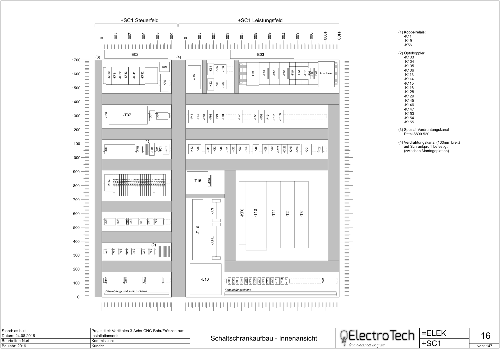
3,858 2019-08-21 10:59:25
Re: Folio sizing and print sizing (7 replies, posted in EN : Help, suggestions, discussions, ...)
Hi Jamis,
draw your schematic like for A4, and try printing on A3 printer.
Columns and rows isn't for printer paper but for scaling element view in your diagrams.
What you see in print preview is what will be normalhy printed, after try use the wole page option, or fit folio to page.
3,859 2019-08-20 21:05:54
Re: Verbindungen innerhalb eines Bauteils (40 replies, posted in DE : Hilfe, Vorschläge, Unterhaltungen...)
I only have this workaround in mind for now, sorry.
I don't know, but in a future we maybe can have possibility to add internal conductor in element, for now I think is very compilcated addon.
We are a little team and only work on our free time at home after work on QET...and owr jobs is very exhausting dependy on days ...
Cheers,
Laurent
3,860 2019-08-20 19:20:16
Re: List of Folios always on 2nd page (14 replies, posted in EN : Help, suggestions, discussions, ...)
NB: is it possible to had button to reload project ?
Why?, delete old folio list pages and generate a new summary page again.
3,861 2019-08-20 19:13:32
Re: DXF import/export coding (8 replies, posted in Export DXF)
Thanks Ronny.
but convertion not read the XML but the mapscene.
I hope Joshua can explain it better than me. ;-)
3,862 2019-08-20 19:10:30
Re: List of Folios always on 2nd page (14 replies, posted in EN : Help, suggestions, discussions, ...)
@Galexis : changed on GIT
3,863 2019-08-20 14:36:47
Re: Kennzeichnung der Betriebsmittel (BMK) (10 replies, posted in DE : Hilfe, Vorschläge, Unterhaltungen...)
3,864 2019-08-20 13:21:48
Re: Symbols rendered in black and white (9 replies, posted in EN : Help, suggestions, discussions, ...)
Great. ;-)
3,865 2019-08-20 13:15:40
Re: List of Folios always on 2nd page (14 replies, posted in EN : Help, suggestions, discussions, ...)
3,866 2019-08-20 08:33:44
Re: Symbols rendered in black and white (9 replies, posted in EN : Help, suggestions, discussions, ...)
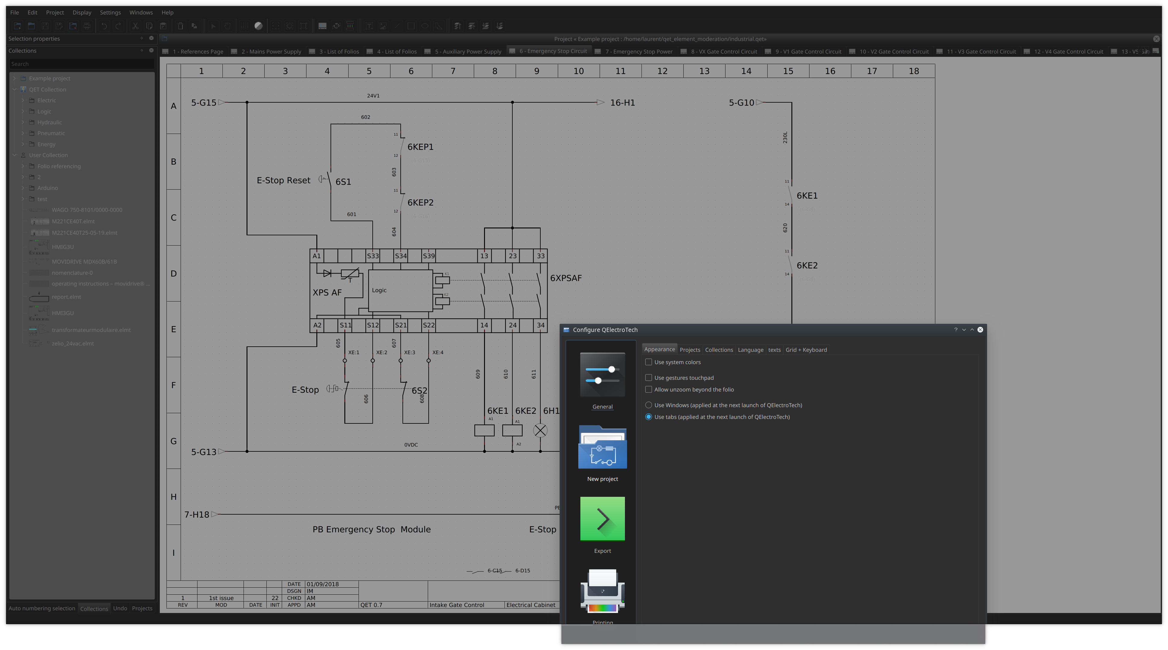
Put this style.css in your ~/.qet folder and disable use system color in settings.
Not perfect but it should be better.
3,867 2019-08-20 08:22:15
Re: Verbindungen innerhalb eines Bauteils (40 replies, posted in DE : Hilfe, Vorschläge, Unterhaltungen...)
Nun meine Frage:
Ist es möglich, innerhalb eines Bauteils diese Anschlüsse so zu verbinden bzw.verknüpfen, dass die Potenziale weitergereicht werden?
Yes possible, you need to add internal conductors above the drawing.And the only way to backup it is keep in project sample.
3,868 2019-08-19 07:40:13
Re: Kennzeichnung der Betriebsmittel (BMK) (10 replies, posted in DE : Hilfe, Vorschläge, Unterhaltungen...)
3,869 2019-08-19 07:21:35
Re: List of Folios always on 2nd page (14 replies, posted in EN : Help, suggestions, discussions, ...)
What do you prefer ?
1 = first postion
2 = second position
3 = 3 position etc,
0 = always in last position
--- sources/projectview.cpp
+++ sources/projectview.cpp
@@ -363,7 +363,7 @@ void ProjectView::addNewDiagram() {
 void ProjectView::addNewDiagramFolioList() {
     if (m_project -> isReadOnly()) return;
     QSettings settings;
-    int i = (settings.value("projectview/foliolist_position").toInt()); //< Each new diagram is added  to the end of the project.
+    int i = (settings.value("projectview/foliolist_position").toInt() -1); //< Each new diagram is added  to the end of the project.
                //< We use @i to move the folio list at second position in the project
     foreach (Diagram *d, m_project -> addNewDiagramFolioList()) {
         DiagramView *new_diagram_view = new DiagramView(d);
@@ -885,7 +885,7 @@ void ProjectView::loadDiagrams()
     // If project have the folios list, move it at the beginning of the project
     if (m_project -> getFolioSheetsQuantity()) {
         for (int i = 0; i < m_project->getFolioSheetsQuantity(); i++)
-        m_tab -> tabBar() -> moveTab(diagram_views().size()-1, + (settings.value("projectview/foliolist_position").toInt()));
+        m_tab -> tabBar() -> moveTab(diagram_views().size()-1, + (settings.value("projectview/foliolist_position").toInt() -1));
         m_project->setModified(false);
     }
 }
--- sources/ui/configpage/generalconfigurationpage.cpp
+++ sources/ui/configpage/generalconfigurationpage.cpp
@@ -55,7 +55,7 @@ GeneralConfigurationPage::GeneralConfigurationPage(QWidget *parent) :
     ui->m_export_terminal->setChecked(settings.value("nomenclature-exportlist", true).toBool());
     ui->m_border_0->setChecked(settings.value("border-columns_0", false).toBool());
     ui->m_autosave_sb->setValue(settings.value("diagrameditor/autosave-interval", 0).toInt());
-    ui->m_foliolist_sb->setValue(settings.value("projectview/foliolist_position", 1).toInt());
+    ui->m_foliolist_sb->setValue(settings.value("projectview/foliolist_position", 2).toInt());

     QString fontInfos = settings.value("diagramitemfont").toString() + " " +
                         settings.value("diagramitemsize").toString() + " (" +
3,870 2019-08-18 21:00:46
Re: Kennzeichnung der Betriebsmittel (BMK) (10 replies, posted in DE : Hilfe, Vorschläge, Unterhaltungen...)
Like this?
With "%prefix%sequ_1-%M%LM" autonum rule.
3,871 2019-08-18 20:48:51
Re: Verbindungen innerhalb eines Bauteils (40 replies, posted in DE : Hilfe, Vorschläge, Unterhaltungen...)
@Plc-user,
Properties for PLC modules are planned, but we have not yet studied or established specifications.
Joshua, the main developer want create new terminal function and terminal block generator before.
3,872 2019-08-18 20:33:19
Re: List of Folios always on 2nd page (14 replies, posted in EN : Help, suggestions, discussions, ...)
Not easy to understand numbering but work very well: 1=second position.
Like PLC (index 0 is the first digit).
Maybe, make a signal when user change spinbox value connected to slots : rebuildDiagramsMap(); updateAllTabsTitle();
I could have done it, the methods already exist in the code, but I do not want the projects to be notified modify without a modification of the user.
3,873 2019-08-18 14:35:20
Re: Verbindungen innerhalb eines Bauteils (40 replies, posted in DE : Hilfe, Vorschläge, Unterhaltungen...)
Thank you for your answer in English.
In principle the wires retain their potentials when they are connected to the same terminals.
Otherwise, I may proceed differently by drawing several overlapping modules with different properties.
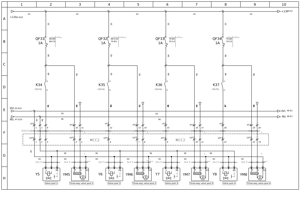
I can not put more examples, but these screenshots can give you ideas. Ps, I removed company tittleblock in this confidential screenshots authors not want I provide these projects..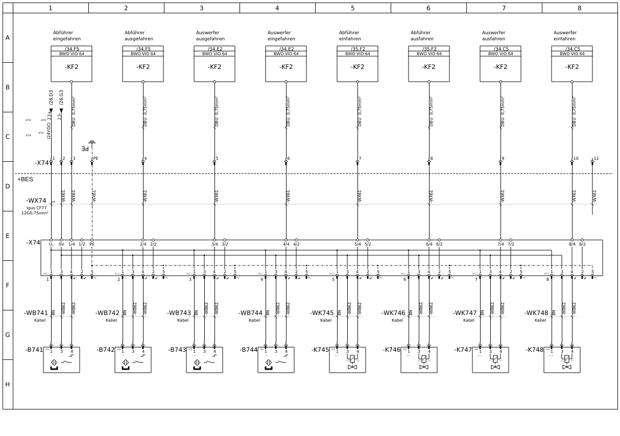
3,874 2019-08-18 13:27:18
Re: Verbindungen innerhalb eines Bauteils (40 replies, posted in DE : Hilfe, Vorschläge, Unterhaltungen...)
Maybe I don't understand well your question?
Maybe this video might interest you and give you ideas...?