You are not logged in. Please login or register.
Active topics Unanswered topics
Search options (Page 101 of 305)
https://qelectrotech.org/forum/viewtopi … 702#p10702
plc-user wrote:You have just experienced the effects I saw in the other thread (internal connections ...)
with "how well the creating software saved the graphic or even in the DXF format"
wrote.
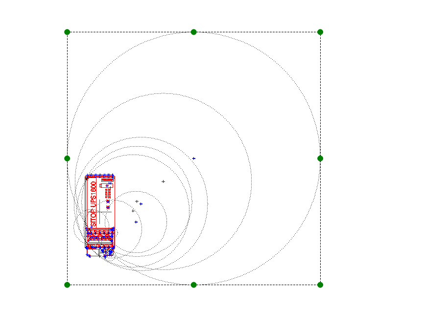
Individual elements of the DXF appear in the graphic as very short lines, but they are
originally very short sections of a circle with a large radius. Hence the huge ones
dashed circles in the QET element ...
I took the bother once and with Inkscape, my favorite drawing program
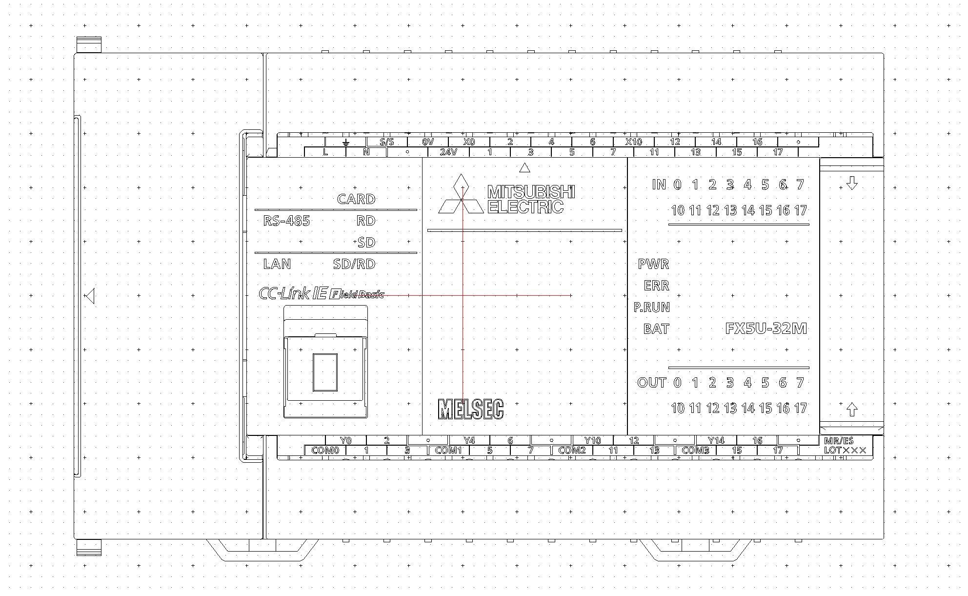
the DXF of the Sitop UPS 1600 is opened. There are front and side views as "symbols"
in front. I then copied the front view and pasted it into a new Inkscape instance.
Now the "symbol" was available as a regular drawing and could again be exported to DXF.
The QET element converted from this now contains almost 7000 individual elements, so
For example, the component cannot be colored because there is no closed contour,
there are no longer any huge circles for minimally short lines ...
My approach for a good QET symbol is this:
Import the DXF file into Inkscape and edit the graphic so that the number
Individual elements will be significantly lower to then use via DXF export from Inkscape
DXFtoQET to create a QET element.
Yes, that sounds awkward, but I find editing with Inkscape to be
more comfortable than with the element editor or other CAD programs. For the
The element editor is then of course indispensable for fine-tuning!
In the appendix you will find the Sitop UPS 1600 - DXF processed as follows:
- opened in Inkscape
- Front symbol copied (Ctrl + C) and pasted into new Inkscape window (Ctrl + V)
- Export to DXF
- an element created with DXFtoQET
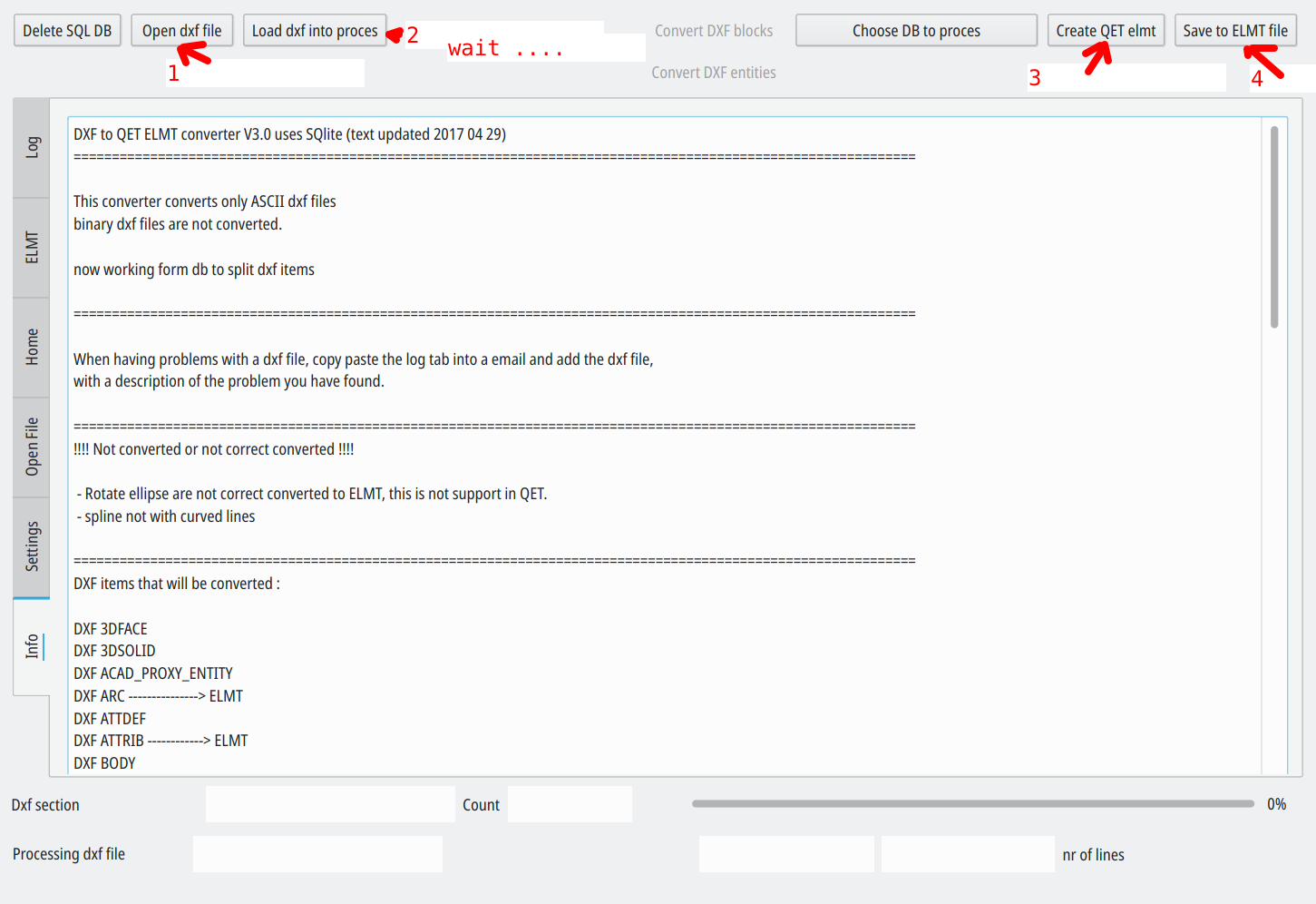
Open your DXF with Inkscape, save to Cutting Plotter (AutoCAD DXF R14)(*.dxf) is better for converter.
If dxf converter crash try other old versions.
If dxf converter crash try other old versions.
After, open converted elmt with QET element editor, remove the terminal added by converter and save (very important for create real element hotspot).
Hello,
try with an simple element not an terminal.
You could share this DXF?
What is the size of your DXF?
Maybe you can reduce the size by editing it and removing unnecessary part with a DXF editor program.
Hi,
you could send your DXF?
Hi

Bonjour et merci,
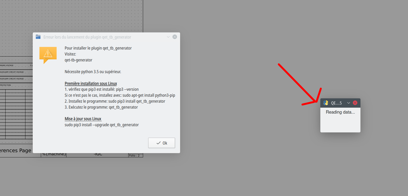
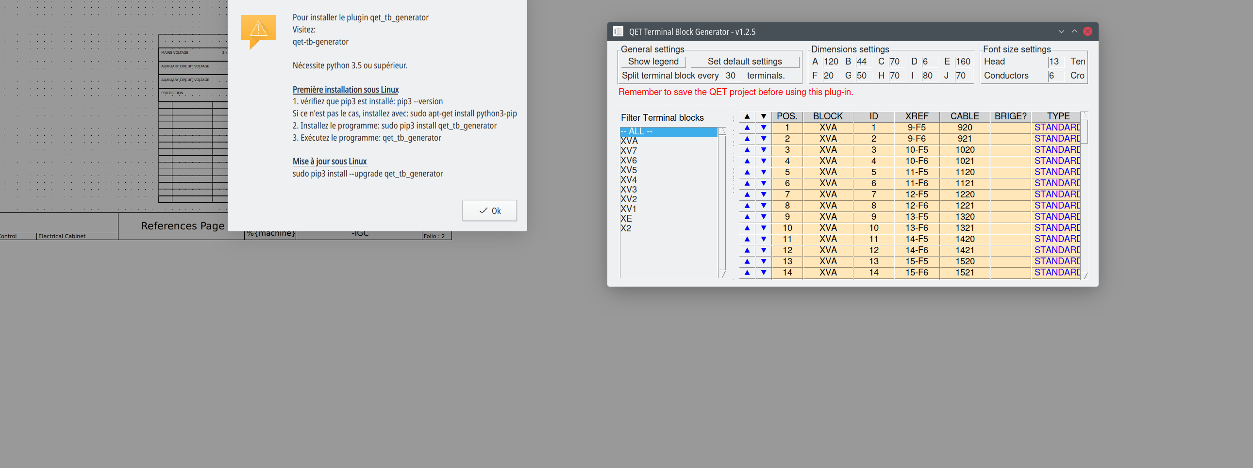
le pop up "pour installer le plug in qet_tb_generator: visitez le site...." à chaque fois, n'indique pas que le plug ne fonctionne pas.
Pour tester le bon fonctionnement suffit de charger le projet exemple industrial.qet fourni et de lancer le plug-in.
Merci.
Afin d'augmenter ma rapidité mettre des conducteurs en bleu d'autres en rouge certains en 2 mm2 d'autres en 1 mm2....
Est il possible ,car je n'ai pas trouvé comment, de copier les propriétés d'un conducteur couleur et épaisseur et de les coller à d'autre comme on fait avec Autocad ?
Si les conducteurs font partie de la même équipotentialité en les reliant par des renvois les propriétés sont conservées, couleur, epaisseur, label, etc.
Yes, change the terminal symbol property to simple in your symbols.
No you can't show contact numbers.
Seems complicated to do.
https://git.tuxfamily.org/qet/qet.git/t … efitem.cpp
Non, pas de raccourci pour l’épaisseur graphique des conducteurs pour l'instant.
Bonjour,
tu peux joindre ton projet?
Sur Linux, OSX, la conf est enregistrée dans un fichier texte facile à manipuler, sur Windows faut aller jouer dans la base de registre ...
Posts found: 2,501 to 2,525 of 7,606
Generated in 0.080 seconds (23% PHP - 77% DB) with 5 queries