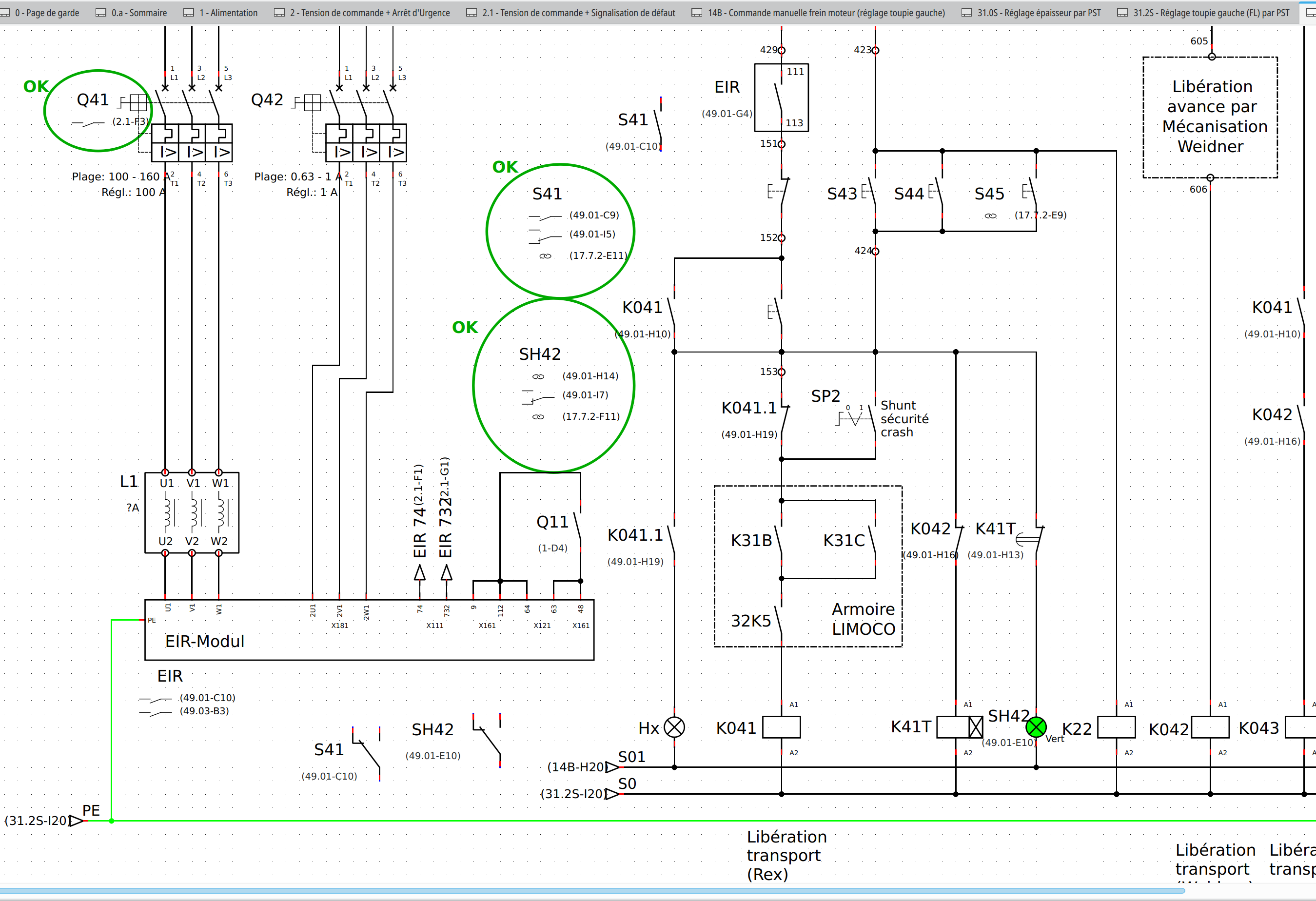
Topic: How to properly link schematic symbol to graphical one?

Hi,

I'm currently trying to create a project for my electric cabinet. This should basically const of two parts: the first one is the schematic and the second one is a "mounting plate" or rather "front view" of the cabinet where I can see individual components (fuses etc).

Schematic is done, but when I add a folio and add a graphical element (for example Eaton FAZ 3P switch), I cannot "link it" to the corresponding symbol in schematics. When I open the symbol in schematics, I see nothing in the "Cross-reference (master)" tab. I tried different naming, filling out most of the fields but no luck.

It should be possible to link those, so I can make sure that I did not miss anything & did not add anything extra, right? Or atleast to "interactively" traverse between the schema & "mounting plate".

QET 0.90

Thanks for your help!

Post's attachments

Attachment icon graphical_symbol_edit.png 210.14 kb, 1 downloads since 2025-11-15 

Attachment icon schematic_symbol_edit.png 177.64 kb, 2 downloads since 2025-11-15 

Re: How to properly link schematic symbol to graphical one?

Hi,

don't use QET 0.90 but 0100-dev!
See this topic for other link for master.
https://qelectrotech.org/forum/viewtopic.php?id=2264
https://download.qelectrotech.org/qet/forum_img_2/other_option_improve5.png

"Le jour où tu découvres le Libre, tu sais que tu ne pourras jamais plus revenir en arrière..."Questions regarding QET belong in this forum and will NOT be answered via PM! – Les questions concernant QET doivent être posées sur ce forum et ne seront pas traitées par MP !

Re: How to properly link schematic symbol to graphical one?

1) use list contact view and not cross for all Xref .
2) For graphical elements change the property thumbnail to slave and select "other"
https://user-images.githubusercontent.com/69154224/175080658-d973a166-4f52-4aba-a7ea-ecdad14da6d0.png

"Le jour où tu découvres le Libre, tu sais que tu ne pourras jamais plus revenir en arrière..."Questions regarding QET belong in this forum and will NOT be answered via PM! – Les questions concernant QET doivent être posées sur ce forum et ne seront pas traitées par MP !

Re: How to properly link schematic symbol to graphical one?

Another workaround :
https://qelectrotech.org/forum/viewtopi … 475#p16475

"Le jour où tu découvres le Libre, tu sais que tu ne pourras jamais plus revenir en arrière..."Questions regarding QET belong in this forum and will NOT be answered via PM! – Les questions concernant QET doivent être posées sur ce forum et ne seront pas traitées par MP !

Re: How to properly link schematic symbol to graphical one?

To explain concisely what the issue is: The default library elements are mostly of type "simple".  In order to link different symbols together, you need to change on to be of type "master", then any other symbol of type "slave" can be linked to it.  There are different categories (organ of protection, contactor, etc.) for the master, but the slave just has a "contact type" property which influences how the xrefs are displayed on the master.

You can import the element from the library and then edit it in your project, switching to a different type.  Or better save it to your user collection for later re-use.  Note that you need to import (place) it again after making changes in the user collection, but the properties on already placed symbols will only change after the project is closed and re-opened.

I usually do this for most of my parts, using the "physical view" for the master element. But I also create most elements myself, such as PLC components comprised of different logical groups, all linked to a physical view of the component.

6 (edited by Vos 2025-11-17 17:08:54)

Re: How to properly link schematic symbol to graphical one?

Aaaah, thanks a lot!

I have edited many devices so they are not "thumbnail" but slave as you wrote.

That brings me to two questions:

1) Do you want my devices so you can bundle them up for other users? I can push them to a git repo or something & you can pull them. I don't care about the license (use them anyway you want). I'm using mostly EATON devices, which could be helpful, especially for european users ...

2) When I link elements together, it creates some strange overlapping label - can I do something to get rid of that?

7 (edited by Vos 2025-11-17 15:10:28)

Re: How to properly link schematic symbol to graphical one?

The image did not upload - second try...

Post's attachments

Attachment icon screenshot-2025-11-17_13-47-15.png 450.81 kb, 2 downloads since 2025-11-17 

Re: How to properly link schematic symbol to graphical one?

That label is the cross-reference back to the "master" device, which can be double-clicked to jump there. It is automatically attached to the "label" dynamic text of the element. So you need to be careful where you place that text.  For the master, it will extend to a list of bound slaves, with one folio reference per slave, also showing the slave's "contact type" property symbolically.

As for contributing the elements, sure you can make a pull request to include it in the standard library, if the quality / consistency is acceptable. However, this pattern of master-slave relationships between the physical and logical symbols is not common among existing library elements.  If you have for example mostly circuit breakers, for which the official library symbol already defines an according element type (master / organ of protection), then it would be kind of useful. But imagine someone not wanting to link it, they could not even give your element a label (as that is not independently possible for slaves). So it would limit the utility of the whole element.

Re: How to properly link schematic symbol to graphical one?

Hi Vos,

you could send a pull request on https://github.com/qelectrotech/qelectr … nt-contrib
https://github.com/qelectrotech/qelectr … ting_plate directory.


Online contreib collection viewer and download.
https://download.qelectrotech.org/qet/e … index.html

"Le jour où tu découvres le Libre, tu sais que tu ne pourras jamais plus revenir en arrière..."Questions regarding QET belong in this forum and will NOT be answered via PM! – Les questions concernant QET doivent être posées sur ce forum et ne seront pas traitées par MP !

Re: How to properly link schematic symbol to graphical one?

acolomb wrote:

That label is the cross-reference back to the "master" device, which can be double-clicked to jump there. It is automatically attached to the "label" dynamic text of the element. So you need to be careful where you place that text.  For the master, it will extend to a list of bound slaves, with one folio reference per slave, also showing the slave's "contact type" property symbolically.

As for contributing the elements, sure you can make a pull request to include it in the standard library, if the quality / consistency is acceptable. However, this pattern of master-slave relationships between the physical and logical symbols is not common among existing library elements.  If you have for example mostly circuit breakers, for which the official library symbol already defines an according element type (master / organ of protection), then it would be kind of useful. But imagine someone not wanting to link it, they could not even give your element a label (as that is not independently possible for slaves). So it would limit the utility of the whole element.

Hallo André,

If you can attach an example of a declassified project, it could help new users and perhaps give old users some ideas.
nomicons/wink

PS: There is no obligation, and I completely understand if you do not wish to disclose your plans or solutions/workarounds.

"Le jour où tu découvres le Libre, tu sais que tu ne pourras jamais plus revenir en arrière..."Questions regarding QET belong in this forum and will NOT be answered via PM! – Les questions concernant QET doivent être posées sur ce forum et ne seront pas traitées par MP !

Re: How to properly link schematic symbol to graphical one?

It would probably mean a huge effort (or not)
but is there no way to link to the element (not for slave elements) an element defined as thumbnail

there is already a base type thumbnail defined
the functionality to add is to link/unlink the element to the thumbnail
the reference to the thumbnail could then be shown next to the label of the element

Always using the latest development version

Re: How to properly link schematic symbol to graphical one?

If I remember correctly, the ‘thumbnail’ type was added only for the SQL database and for the Boom table in order to count only one element in entire the project with the same label.
Not the physical representation element for nomenclature list, off course is the same element!

"Le jour où tu découvres le Libre, tu sais que tu ne pourras jamais plus revenir en arrière..."Questions regarding QET belong in this forum and will NOT be answered via PM! – Les questions concernant QET doivent être posées sur ce forum et ne seront pas traitées par MP !

13

Re: How to properly link schematic symbol to graphical one?

You're right Laurent, I should make a sample of these elements and how I use them. Maybe I can extract some folios from my current project at $work which use a Beckhoff PLC and each component is handled this way.

Will try to find some time the next months and post back here.

EDIT: Scratch that, I already did upload an example in 2023:
https://qelectrotech.org/forum/viewtopi … 617#p18617