Topic: How to properly link schematic symbol to graphical one?
Hi,
I'm currently trying to create a project for my electric cabinet. This should basically const of two parts: the first one is the schematic and the second one is a "mounting plate" or rather "front view" of the cabinet where I can see individual components (fuses etc).
Schematic is done, but when I add a folio and add a graphical element (for example Eaton FAZ 3P switch), I cannot "link it" to the corresponding symbol in schematics. When I open the symbol in schematics, I see nothing in the "Cross-reference (master)" tab. I tried different naming, filling out most of the fields but no luck.
It should be possible to link those, so I can make sure that I did not miss anything & did not add anything extra, right? Or atleast to "interactively" traverse between the schema & "mounting plate".
QET 0.90
Thanks for your help!
![]() graphical_symbol_edit.png 210.14 kb, 38 downloads since 2025-11-15
graphical_symbol_edit.png 210.14 kb, 38 downloads since 2025-11-15
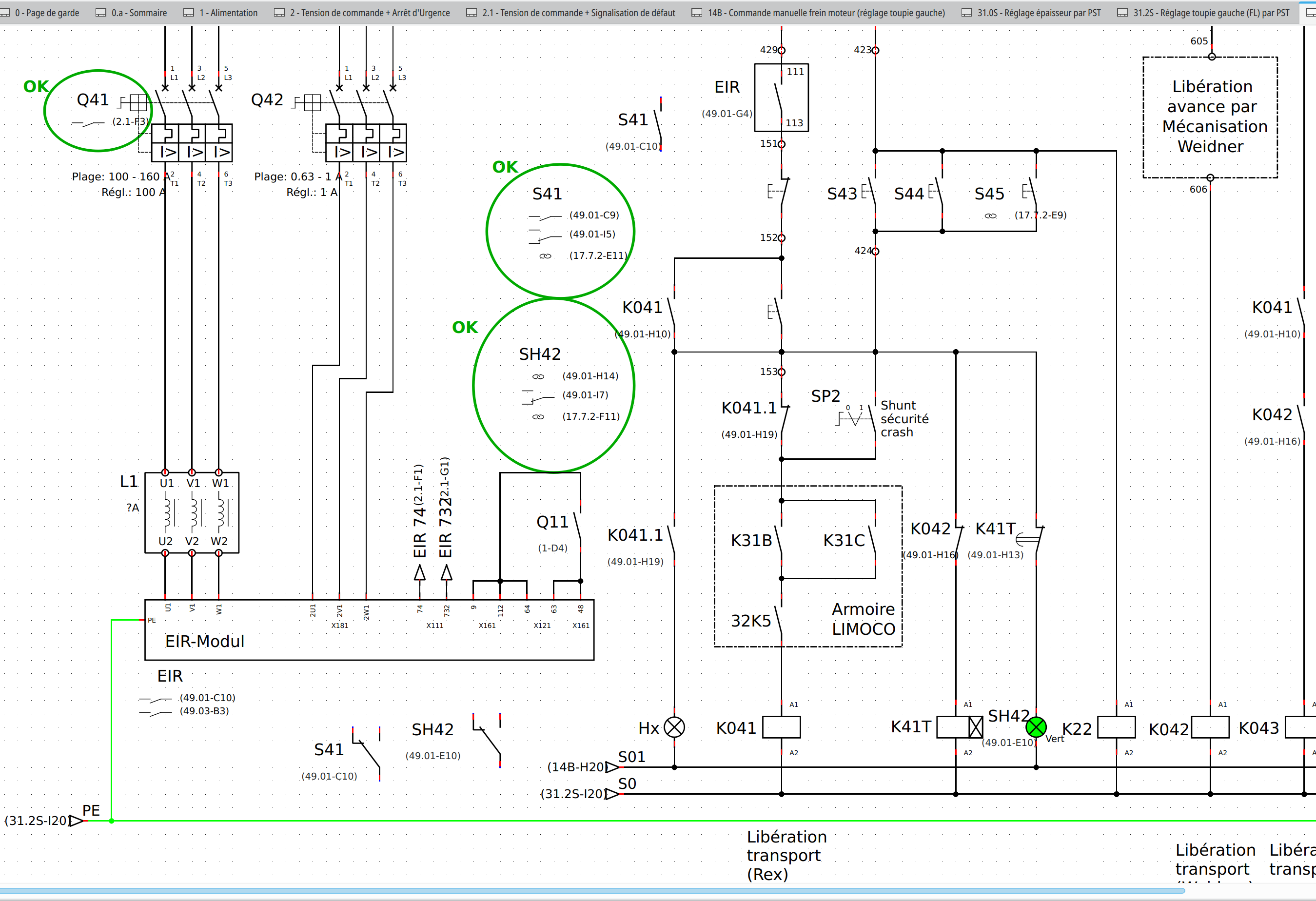
![]() schematic_symbol_edit.png 177.64 kb, 42 downloads since 2025-11-15
schematic_symbol_edit.png 177.64 kb, 42 downloads since 2025-11-15