How did you generate this list?
scorpio810 wrote:

You are not logged in. Please login or register.
QElectroTech → Posts by kakas
Pages 1
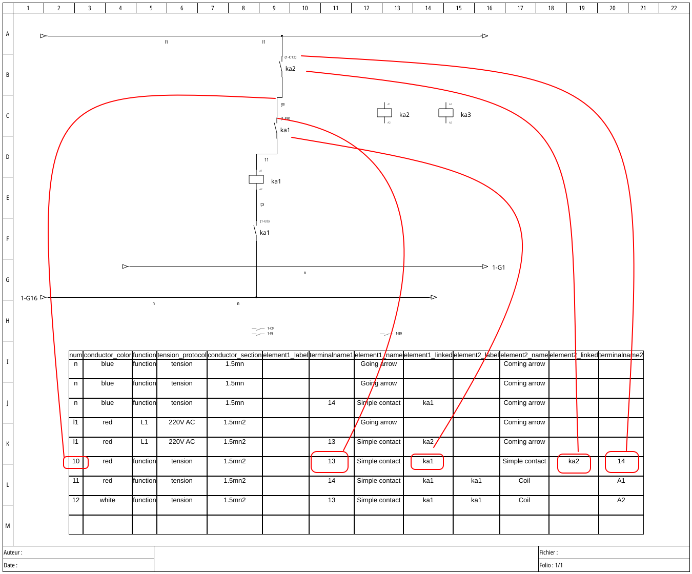
How did you generate this list?
Thank you, after reading the posts in the referred topics it seems to me that preparing the list is not an issue if the wire is not going to an other folio. If it does, then some programming is required, which is not availabe as a ready-to-use solution yet. Is it correct?
I see in the 0.1 version that wire list can be exported.
We need a more advanced list, where each wire is listed with the ID of two end connection. Like if one end of wire V1 is connected to A1 of K1 relay, other end is to A2 of K2 then it is listed something like:
V1 - K1.A1 K2.A2
Based on this list we produce the labels to be attached to the end of the wires requested by the client.
Is it possible to do that?
Thank you, in this way at least a visual indication of the wiring is possible.
In our case if we have let's say 5 relays with their A1 terminal connected to -120V, then it is made in the way, that one of A1 is connected to -120V, the others are linked from that A1 with twin wire shoes. This is to be indicated in the drawing, moreover, we have to export the wire list, which indicates the start and end of each and every wires, and also we print the wire labels to be attached each wire end.
If Y connection on the drawing is not supported, then we cannot specify it. The 100 cabinets produced will have different wirings according to which is made by which person. Electrically they will be the same, but wiring is different, which is not accepted in our case.
First of all, I would like to sincerely congratulate you on the great work you have done.
I am just getting familiar with the software.
Is there a way to indicate connection of two wires to one terminal? It is a common practice, and indicating it in the drawing helps a lot in the field.
Pages 1
QElectroTech → Posts by kakas
Powered by PunBB, supported by Informer Technologies, Inc.
Generated in 0.008 seconds (73% PHP - 27% DB) with 5 queries