Table of Contents
Features
This page lists the features of all past and presents QElectrotech versions as the improvments for future version. For the time being, you will see the features for version 0.1.
Version 0.1
Basics
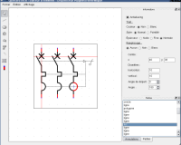
QET allows you to lay an element on a schema, link the conductors. The schema has a cartocuche where you can edit the data. You can move and rotate elements. The conductors that link the elements are laid with the mouse. The path is editable. You can change the parameters of the conductors: they can be simple, with one cable or with several cables. The software deals automatically with junction points between conductors. You can also add independant text fields on the schemas.
Collections of elements
The elements comes from element collection. On the one hand, there is a common collection meant to be shared between several users and to be not editable without administrator rights. On the other hand, there is the user collection, meant to be related to one user. Schemas keeps references to only these elements. Thus, it is not possible to open completely a schema using a unknown element (i.e. an element that is nor in the common collection, nor the user collection). The user must keep attention and give the possible missing elements when he sends his schema.
Elements managment
QET allows you to add, edit, remove elements that are in collection. A wizzard helps you in the creation of a new element and a decdicated element allow you to draw elements.
Schema export as a picture
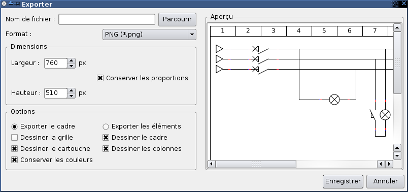
The schemas can be exported in the following formats: bitmap, JPEG, PNG and SVG. Options allow you to export (or not) the grid, cartouche, borders, columns, etc.
Printing
There is a simple support for printing. By default, aschema that is too big is cut and printed on several pages. The schemas can be adapated to the page size on demand. Under X11, printing requires the packet cupsys-bsd. It is possible to draw to a PDF file directly under X11. Under Windows, you can use PDFCreator.
Systray integration
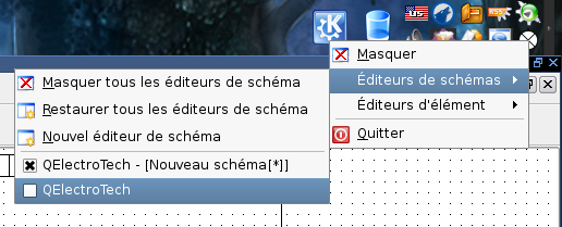
QElectroTech adds an icon to the systray (the small zone that is typically next the clock) that allows you to manage your windows: schema editor and element editor.
Roadmap
Making the roadmap was not easy because QET is a new software with few devloppers, but that deals with a field that needs a lot of features that are not always very simple.
For all QET we will try to add:
- a major feature, i.e. something that really needed in electrotechnic field and that relativly urgent and/or complex to develop.
- a minor feature, i.e. a usefull feature but that is not a necessity or that is of minor importance ;
- 0 to 2 significant improvment(s) to the graphical interface, user-friendlinesse and/or software behaviour.
Here are the planned features for the next version of QET:
Version 0.11
- Bug fixing
- Bug #15: Bad position for text field on schemas ;
- Bug #16: Bad managment of text edits of a conductor.
- Features:
- The software is launched only once per user ; so, it is possible to managae all the schema and element editors trhough a unique icon in the systray.
- The program can also directly open (i.e launching with arguments) files with elements.
- The association of *.qet and *.elmt would be made easier ; *.desktop files are installed under X11 while a program for saving is provided with the Windows version.
- Addition of a menu with access to the recently open files.
- UNIX manual (`man qelectrotech').
Version 0.2
- Possibility to change the line endings in the element editor (circle, square, arrow, etc).
- Mask the file system while saving elements.
- Possibility to add several elements in a *.qet file. It is then called a project file. All project files can also include elements that are specific to the project. The user is then no more required to make sure that there are no missing elements in the collection.
Version 0.3
- Addition of devices: a device symbole is a rectangle that encloses several elements. There are connectors on the rectangle.
- Possibility to center texts.
- Daemon mode: possibily to stay in the systray without windows.
Version 0.4
- Possibility to add dotted lines between contacts, thermal relays and/or coils to state the relation between them.
- Possibility to use rich text in the schemas.
Version 0.5
- Export in DXF format.
- Possibility to make cut/paste in the element editor.


